1. How do programmable DC switching power supplies differ fundamentally from linear power supplies?
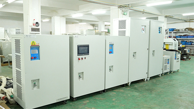
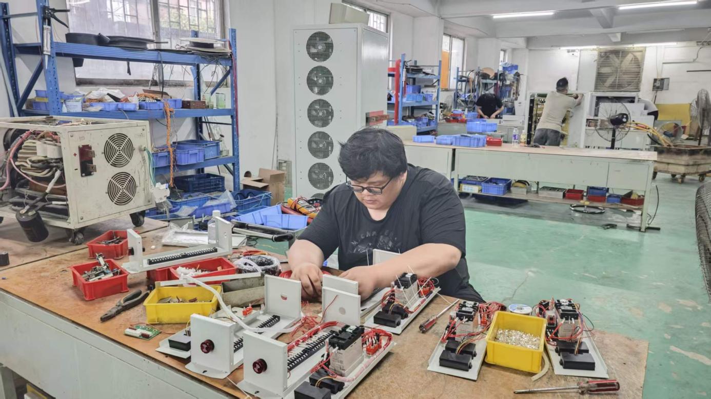
Programmable DC switching power supplies utilize high-frequency pulse-width modulation (PWM) through power MOSFETs or IGBTs to chop incoming rectified AC voltage, followed by a high-frequency transformer and filtering stage. This delivers electrical efficiency typically around 90%, reduces cabinet physical weight and footprint by up to 70%, and accommodates high-power loads (from kilowatts up to megawatts). Linear supplies, by contrast, drop voltage across transistors operating in their active ohmic region, which creates extreme thermal losses, limits practical efficiency to 40%–50%, and makes units excessively heavy. While linear supplies historically offered lower output ripple, modern switching supplies with advanced multi-stage LC filters achieve low RMS ripple (≤ 0.1%–0.3%) suitable for virtually all high-power automated testing and electrochemistry.
2. What is the difference between Constant Voltage (CV), Constant Current (CC), and Constant Power (CP) modes?
In Constant Voltage (CV) mode, the supply maintains the user-programmed output voltage regardless of how the load resistance fluctuates, provided the current drawn remains beneath the programmed current limit. If the load impedance drops and current reaches the limit, the supply automatically crosses over into Constant Current (CC) mode, capping current at the setpoint and dropping the output voltage dynamically. Constant Power (CP)—also referred to as autoranging—automatically adjusts voltage and current along a constant hyperbolic wattage envelope (V × I = Pmax). This enables testing at high voltage/low current or low voltage/high current using a single supply, eliminating the need to purchase multiple dedicated power sources.
3. Why is transient recovery response time critical for automotive and component testing?
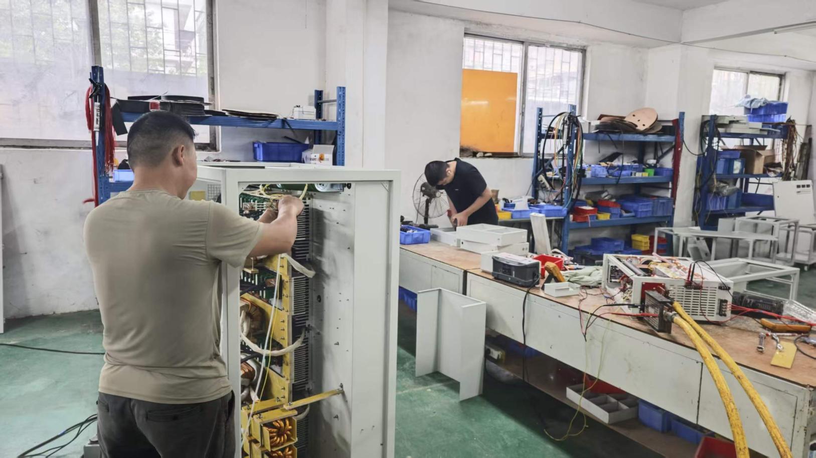
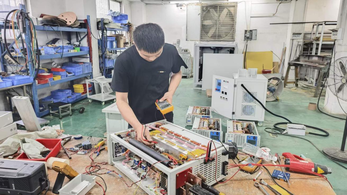
Transient recovery time measures how rapidly the power supply output voltage stabilizes back within a specified band (typically 0.1% or 50mV) following a drastic step change in load current (such as a 10% to 90% load surge). In electric vehicle motor drives, DC-DC converter qualification, and inverter validation, high inrush currents can cause poorly regulated power supplies to sag severely or overshoot. Severe overshoots can trigger the Device Under Test’s (DUT) internal Over-Voltage Protection (OVP) or destroy sensitive silicon. High-speed DSP-controlled switching supplies from Guangdong Fenvix Technology Co., Ltd. maintain tight sub-millisecond loop response times to guarantee DUT integrity during aggressive step testing.
4. Which digital communication interfaces are recommended for automated production lines (ATE)?
For bench setups and small automated cells, standard RS485 (with Modbus-RTU) or isolated USB (virtual COM/SCPI) provides cost-effective, noise-immune communication over moderate cable runs. For expansive industrial production plants and high-speed ATE racks, isolated Ethernet / LAN (Modbus-TCP or LXI/SCPI) or CANopen is strongly recommended. Ethernet enables real-time deterministic polling across local network subnets, isolates ground loops between computing mainframes and high-voltage power stages, and ensures frictionless software integration using Python, C#, or LabVIEW.
5. How should buyers configure thermal management: forced air cooling vs. closed-loop water cooling?
Forced air cooling is optimal for typical clean-room laboratories, research institutions, and dry manufacturing facilities where ambient ambient temperatures stay beneath 40°C and corrosive atmospheric agents are absent. In contrast, water/liquid cooling is strongly recommended for heavy electroplating, metal refining, hydrogen electrolysis, or continuous high-power testing environments (>30kW). Water-cooled cabinets can be fully sealed (IP54 or higher), shielding critical IGBTs, gate drives, and control boards from airborne acid vapors, corrosive moisture, and conductive metal dust, while significantly extending system MTBF (Mean Time Between Failures).
6. Can multiple programmable DC switching supplies be connected in series or parallel?
Yes, but only if the power supply design explicitly supports active master-slave sharing. For parallel configurations (increasing current), units must link via a dedicated high-speed analog/digital bus to ensure the master unit balances current delivery across slaves (<1% typical error), preventing a single unit from absorbing the bulk of thermal stress. For series configurations (increasing voltage), internal diodes and insulation ratings to chassis ground must be verified to prevent the floating output potential from exceeding internal component breakdown limits. Guangdong Fenvix Technology Co., Ltd. configures built-in reverse-polarity protection and multi-chassis synchronization buses on all modular high-power orders.
7. What essential electrical parameters must be confirmed when requesting a custom quote?
To receive an exact, optimized proposal, please share: (1) AC input utility ratings (e.g., 380V, 415V, or 480V 3-phase, 50/60Hz); (2) Desired DC output boundaries (maximum voltage, maximum continuous current, total power); (3) Operational mode requirements (CV, CC, CP, or auto-reversing); (4) Maximum allowable ripple/noise (RMS or peak-to-peak); (5) Remote interface preferences (RS485, LAN, CAN, analog 0-10V); (6) Cooling environment (ambient temperature, forced air vs. water availability); and (7) Required safety approvals (CE, RoHS, LVD, EMC).