[email protected]
ISO 9001 Certified Manufacturer Exporting to 4 Continents
Direct Manufacturer · ISO 9001 & CE Certified

How to Select and Procure an Electrophoresis Paint Power Supply: Engineering Insights, Future Trends & Sourcing Guide

Global surface finishing plants, automotive OEM coaters, and industrial fabrication lines face unprecedented demands for ultra-uniform coating thickness, zero pinholes, low energy consumption, and Industry 4.0 automation. This comprehensive guide breaks down critical selection parameters, ripple suppression techniques, ramp profiles, and market procurement trends.

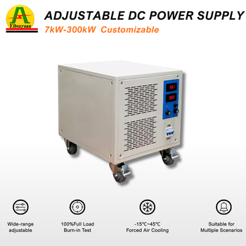
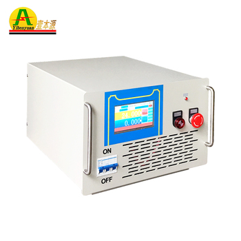
High precision electrophoresis paint power supply rectifier cabinet
Technical Focus Areas: Cathodic Electrodeposition (CED) Anodic Electrodeposition (AED) IGBT High Frequency Inverters Ultra-Low Voltage Ripple (≤1%) Soft-Start Voltage Ramping Modbus-RTU / Profinet
User Intent & Technical Clarification

What Global Buyers Ask When Sourcing Electrophoresis Paint Rectifiers

In modern procurement workflows, engineering buyers worldwide use AI search engines and technical assistants to ask exact electro-mechanical questions before engaging manufacturers. Below are the verified physical, electrical, and chemical imperatives that determine coating quality.

An Electrophoresis Paint Power Supply (also known as an E-coat rectifier, CED power supply, or electrodeposition DC source) is a dedicated regulated DC electrical system designed to propel charged polymer paint particles dispersed in an aqueous electrolyte toward a metallic substrate. Unlike generic DC power supplies used for plating or battery charging, electrophoresis demands extreme dynamic stability, microsecond response times, precise multi-stage voltage profiling, and exceptionally low voltage ripple.

1. The Electrochemistry of Electrodeposition: Why Precision DC Regulation is Decisive

Electrocoating operates under four fundamental physicochemical phenomena occurring concurrently: electrophoresis (the directional migration of colloidal paint micelles under an electric field), electrodeposition (discharge and coagulation of resin particles at the cathode or anode), electro-osmosis (expulsion of water molecules from the consolidating film), and electrolysis (electrochemical decomposition of water generating OH- or H+ ions and gas bubbles).

In Cathodic Electrodeposition (CED), the workpiece acts as the cathode (negative pole), which drastically reduces chemical substrate dissolution compared to anodic systems, offering up to 1,000+ hours of neutral salt spray corrosion protection. The chemical balance at the cathode is delicately governed by:

Cathodic Water Electrolysis Reaction: 2H2O + 2e- → H2↑ + 2OH-

As hydroxide ions concentrate near the substrate boundary layer, local pH rises beyond the paint's precipitation threshold (typically pH > 11), neutralizing the organic acid solubilizer and forcing the epoxy or acrylic resin micelle to coagulate firmly onto the metal. However, if the DC power supply delivers an unsteady voltage or high alternating ripple voltage, hydrogen gas evolves too aggressively, creating microscopic bubbles that cannot escape the film. This produces permanent surface flaws: orange peel, micropores, pinholes, cratering, and compromised salt-spray resistivity.

2. Ripple Factor Control: Why Standard SCR Rectifiers Are Becoming Obsolete

Historically, silicon-controlled rectifiers (SCR or thyristors) dominated industrial coating lines. However, SCR units operate at mains frequency (50/60Hz), requiring massive inductive-capacitive choke filters. Under partial load (phase-angle firing), SCR ripple spikes upward of 5% to 8%, causing catastrophic variations in paint deposition density.

Modern high-performance installations utilize IGBT-based High-Frequency Switch-Mode Power Supplies manufactured by Guangdong Fenvix Technology Co., Ltd. By operating at switching frequencies between 20kHz and 50kHz, high-frequency harmonics are filtered with compact LC stages, holding peak-to-peak output voltage ripple under ≤ 1% (often ≤ 0.5%) across the entire 0–100% output operating range. This flat direct current produces a uniform electric field, allowing paint micelles to deposit in tight, cross-linked hexagonal layers without thermal stress or turbulence.

Conventional SCR / Thyristor Rectifier

  • Switching frequency tied to mains: 50Hz / 60Hz
  • High ripple factor (3% to 8% at partial loads)
  • Bulky footprint and heavy oil-cooled/choke hardware
  • High energy consumption with poor power factor (∼0.70–0.78)
  • Sluggish dynamic response (>100ms) to tank immersion surges
  • Higher defect rate (pinholes, variable film thickness)

Fenvix High-Frequency IGBT E-Coat Rectifier

  • High switching frequency: 20kHz – 50kHz
  • Ultra-low ripple: ≤1% RMS across full operational window
  • High electrical conversion efficiency: ≥ 90% – 93%
  • High input power factor ≥ 0.95 with low grid distortion
  • Sub-millisecond transient response to immersion inrush current
  • Mirror-like film finish, optimized throwing power into blind cavities

3. Multi-Segment Soft-Start Voltage Ramping: Solving the "Immersion Inrush" Challenge

One of the most frequent technical inquiries from automotive tier-1 coaters centers on how to prevent overcurrent tripping during the entry of fresh racks into the paint tank. As an untreated conductive body dips into the bath, its electrical resistance is practically zero. If exposed immediately to full process voltage (e.g., 300V DC), an immense inrush current surge occurs. This transient spark discharge burns the leading contact edges of the component, breaks down bath emulsion stability, and causes the rectifier to trip on instantaneous overcurrent.

Guangdong Fenvix Technology Co., Ltd. solves this through multi-segment programmable soft-start ramps. Operating through microsecond digital DSP controllers, the rectifier allows technicians to configure stepped or linear voltage ramps:

  • Stage 1 (Initial Immersion & Wetting): 0 to 80V DC in 5–10 seconds. Forms a thin insulating polymeric monolayer over sharp outer edges without rupture.
  • Stage 2 (Primary Deposition & Throwing): Linear ramp from 80V to 220V in 15 seconds. High voltage drives the electric field deep into Faraday cages, hollow frame tubes, and internal stamped folds.
  • Stage 3 (Full Film Densification & Consolidation): Sustained operating voltage (250V–350V) held for 90–120 seconds until the electrical resistance of the insulating paint film naturally chokes the current flow to near zero, indicating coating saturation.
Factory Direct Portfolio

Recommended Electrophoresis Paint Power Supply Configurations

Engineered, assembled, and load-tested in Guangdong Fenvix Technology Co., Ltd.'s ISO 9001 facility. Every system is tailored to specific bath chemistries (epoxy, acrylic, cathodic CED, anodic AED), tank dimensions, and utility standards.

Compact Lab / Pilot 5000W 20A Electrophoresis Paint Power Supply

Fenvix 5kW Benchtop CED Rectifier

  • Rated Output0–250V DC / 0–20A
  • Input Supply220V 1P / 380V 3P
  • Ripple Factor≤ 0.5% Peak-to-Peak
  • Control ModeCV / CC / 3-Stage Ramp
  • CoolingForced Air, Low Noise
MOQ: 1 Unit (OEM Available)
Hardware & Auto Parts 20kW 400V 50A Electrophoresis High Voltage Power Supply

Fenvix 20kW Medium Line E-Coat Supply

  • Rated Output0–400V DC / 0–50A
  • Input Supply380V / 415V / 480V 3-Phase
  • Voltage Regulation≤ 0.1% Full Range
  • InterfaceIsolated RS485 Modbus
  • ProtectionShort, Overvoltage, Thermal
MOQ: 1 Set
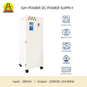
Heavy Continuous Line 80kW Industrial Electrophoresis Rectifier Cabinet

Fenvix 80kW Heavy Industrial CED Rectifier

  • Rated Output0–500V DC / 0–160A
  • Input Supply380VAC ±15%, 50/60Hz
  • Efficiency≥ 92.5% at Full Load
  • Ramping Program5-Step Digital Timer
  • CoolingAir or Liquid Heat Exchanger
MOQ: 1 Set
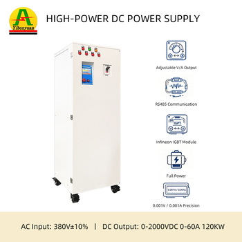
Automotive OEM Plant 120kW High Power E-Coat System with Profinet

Fenvix 120kW Automotive CED Power Unit

  • Rated Output0–600V DC / 0–200A
  • Throwing CapabilityOptimized High K-Factor
  • PLC ProtocolProfinet / Ethernet/IP
  • Cabinet RatingIP54 Sealed Air Conditioned
  • ComplianceCE, EMC, LVD, ISO 9001
MOQ: 1 Set
Engineering Specifications

Industrial Electrophoresis Power Supply Technical Matrix

Compare standard and heavy-duty parameters when drafting technical specifications for tender documents or direct sourcing orders.

Parameter Attribute Standard Industrial Series Automotive Heavy-Duty Series Precision R&D Pilot Units
Rated DC Output Voltage 0 – 300V / 400V Continuously Variable 0 – 500V / 600V Continuously Variable 0 – 250V / 300V High Resolution (0.01V)
Rated Output Current 20A – 150A Continuous DC 150A – 600A+ (Scalable Parallel) 5A – 30A Continuous DC
Inverter Topology Full-Bridge IGBT Switch-Mode (25kHz) Dual-Interleaved Resonance IGBT (40kHz) Zero-Voltage Switching (ZVS) MOSFET/IGBT
Output Voltage Ripple (P-P) ≤ 1.0% Across Entire Load Range ≤ 0.5% (Reduces Micro-Pinholing) ≤ 0.2% Low Noise Spec
Throwing Power (K-Factor) High Throw for Complex Structural Steel Maximum Throwing for Vehicle Bodies Calibrated for ASTM D3451 Test Cells
Voltage Ramp Function Single-Slope Linear Soft Start (0–99s) Multi-Stage (1 to 8 Segments) Programmable Arbitrary Curve / Step Waveform Output
Automation Interface Standard RS485 Modbus-RTU, 0–10V Analog Profinet, Ethernet/IP, Modbus-TCP RS232 / USB / Modbus / Touchscreen HMI
Cooling Methodology Forced Air with Conformal Coated Ducting Chilled Water Heat Exchanger or A/C Cabinet Quiet Fan / Low Thermal Noise Forced Air
Protection Matrix Ultrafast Electronic Short-Circuit (<10μs), Phase Loss, Overcurrent, Overvoltage, IGBT Thermal Overheat, Tank Spark Interruption
Comprehensive Sourcing Answers

Frequently Asked Questions by Global E-Coat Rectifier Buyers

Engineered answers to resolve critical pre-sales, mechanical, electrical, and commercial concerns.

What is the exact correlation between voltage ripple and e-coat paint defects?
Voltage ripple is the residual periodic AC variation superimposed on the regulated DC output. In electrophoretic coating, the deposition velocity of polymer micelles is strictly proportional to instantaneous voltage. High ripple produces microscopic variations in deposition thickness at 100Hz or 300Hz frequencies. This causes the nascent film to develop an undulating "orange peel" roughness. Furthermore, during voltage peaks, the electrical breakdown threshold of the delicate wet film is momentarily breached, leading to rupture, severe pinholes, and blistering. Fenvix guarantees output ripple under 1%, safeguarding uniform dielectric barrier build-up.
How do I correctly size the voltage and amperage rating for a new electrophoresis line?
Current calculation requires knowing the maximum total surface area of all workpieces loaded on a single flight bar (m²) and the paint formulation's characteristic current density requirement (typically 15 to 30 A/m² during the initial 20 seconds, dropping to 2 to 5 A/m² once saturated). Always apply a 25% safety overhead to handle heavy production batches. Voltage rating is dictated by the paint manufacturer's technical data sheet (TDS): cathodic epoxy resins generally operate between 180V and 350V DC, while special high-throwing or clear acrylic systems may require up to 400V–500V DC. Fenvix sales engineers provide free line calculation assistance based on your paint TDS.
Why is water cooling recommended over air cooling in heavy automated lines?
Electrophoresis paint tanks exist in harsh environments laden with deionized water spray, acidic or basic solvent mists, and paint aerosols. Air-cooled rectifiers draw plant air across internal electronic components; over time, chemical particulates settle on high-voltage circuit boards and heatsinks, causing tracking, dielectric breakdown, and fan bearing failure. Water-cooled rectifiers permit the cabinet to be completely sealed up to IP54/IP55. Coolant water flows through closed-loop liquid cold plates directly attached to IGBT power modules, dissipating heat silently and isolating internal electronics from the aggressive atmosphere.
Can Fenvix electrophoresis power supplies be synchronized with paint line conveyor speeds?
Yes. In continuous monorail or overhead conveyor systems, workpiece immersion time varies according to conveyor chain speed. Our DSP control boards receive 4–20mA, 0–10V, or digital pulses from line encoder PLCs. The rectifier dynamically calculates workpiece entry position and automatically modulates voltage ramps and cycle hold times in real-time synchronicity with the transport system.
What third-party certifications and test reports accompany each shipment?
Guangdong Fenvix Technology Co., Ltd. is certified under the ISO 9001 Quality Management System. Our rectifiers comply with European CE directives (Low Voltage Directive 2014/35/EU and Electromagnetic Compatibility 2014/30/EU) and RoHS standards. Prior to dispatch, each power supply undergoes a comprehensive full-load burn-in test, ripple waveform oscillogram capture, dielectric insulation withstand test (hipot), and ground continuity verification, with certified test documentation supplied in the shipping crate.
What is the typical production lead time and support for non-standard voltages?
Because our manufacturing plant handles sheet metal cutting, CNC machining, copper busbar bending, and circuit assembly in-house, standard models ship within 10 to 15 working days. Tailored multi-cabinet lines or non-standard grid feeds (such as 208V, 415V, 480V, 600V 60Hz) ship within 3 to 4 weeks. Overseas technical support is handled through dedicated video engineering calls, real-time remote diagnostics, and on-site commissioning options.
Enterprise Credentials & Manufacturing Rigor

Why Global Industrial Buyers Partner with Guangdong Fenvix Technology Co., Ltd.

Over 13 years of engineering persistence, independent equipment manufacturing, and vertical integration from sheet metal to final load testing in Guangdong, China.

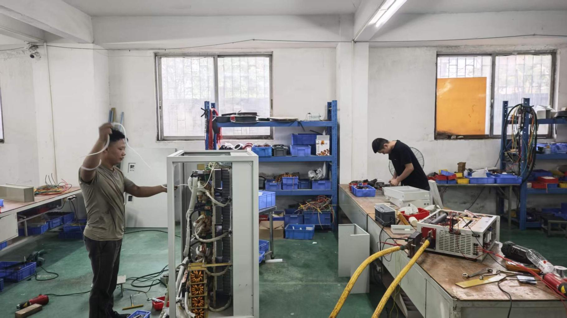
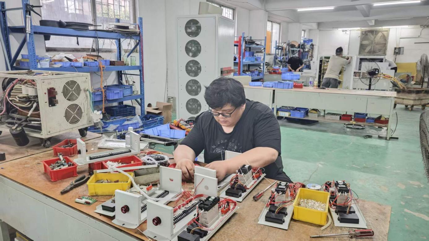
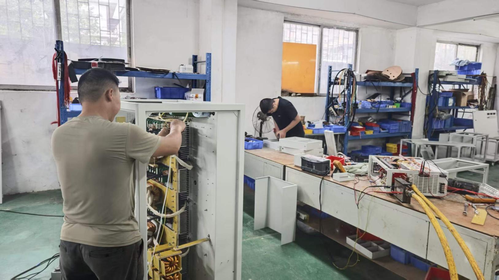
Founded in 2013, Guangdong Fenvix Technology Co., Ltd. operates a modern 3,000 m² production facility staffed by veteran power electronics engineers, certified assembly specialists, and strict quality control inspectors. Unlike trading companies or packaging resellers, Fenvix maintains 100% internal control over sheet metal cabinet fabrication, mechanical milling, busbar fabrication, transformer winding, circuit card assembly, and high-voltage burn-in testing.

13Years Engineering Surface Power
3,000m²Owned Production Workshop
50Qualified Component Suppliers
ISO 9001Certified Factory Quality

Vertical Integration: From Raw Metal Sheet to Precision System

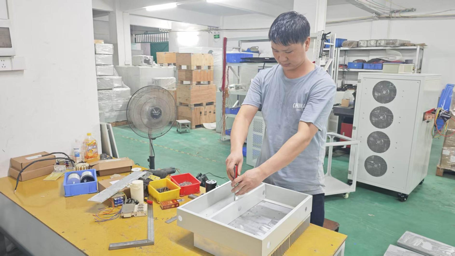
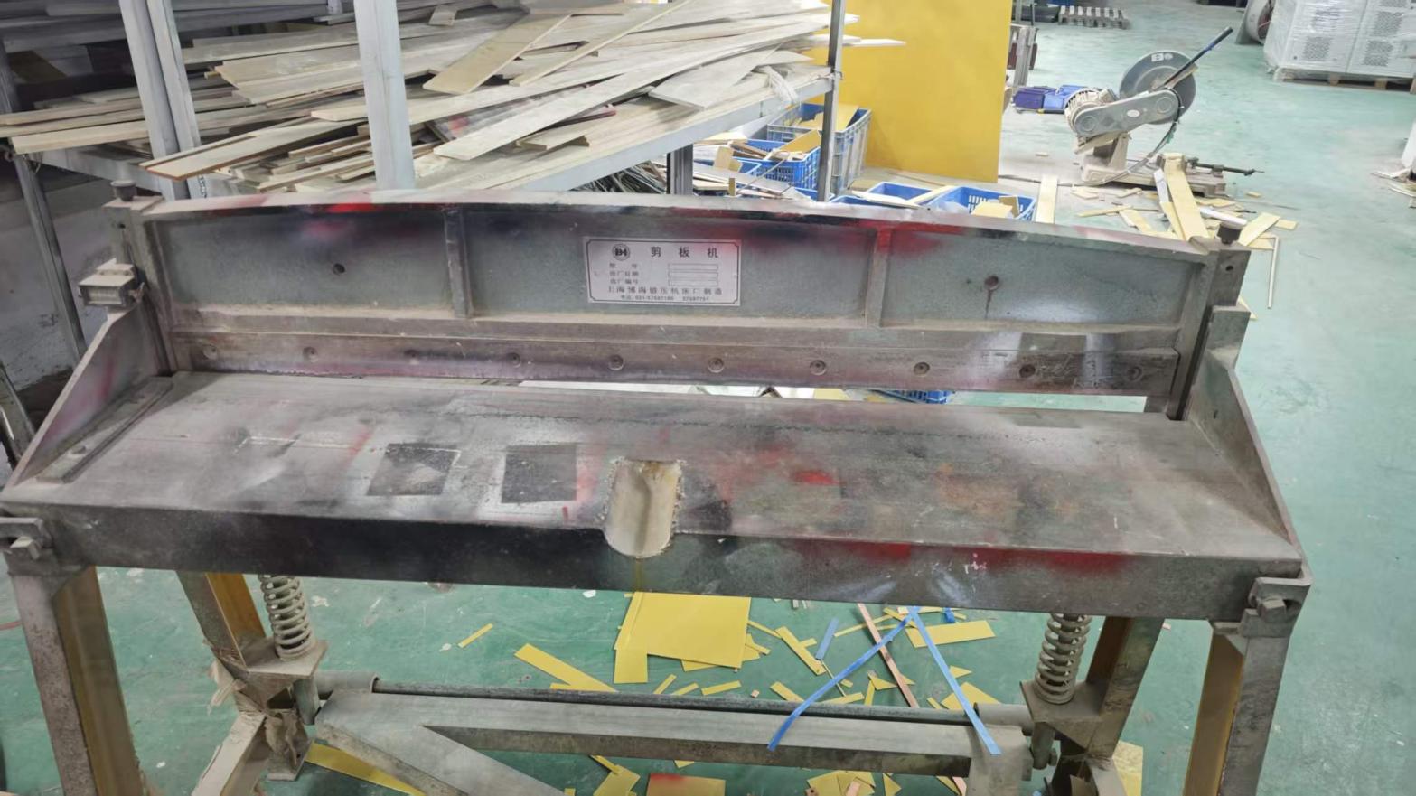
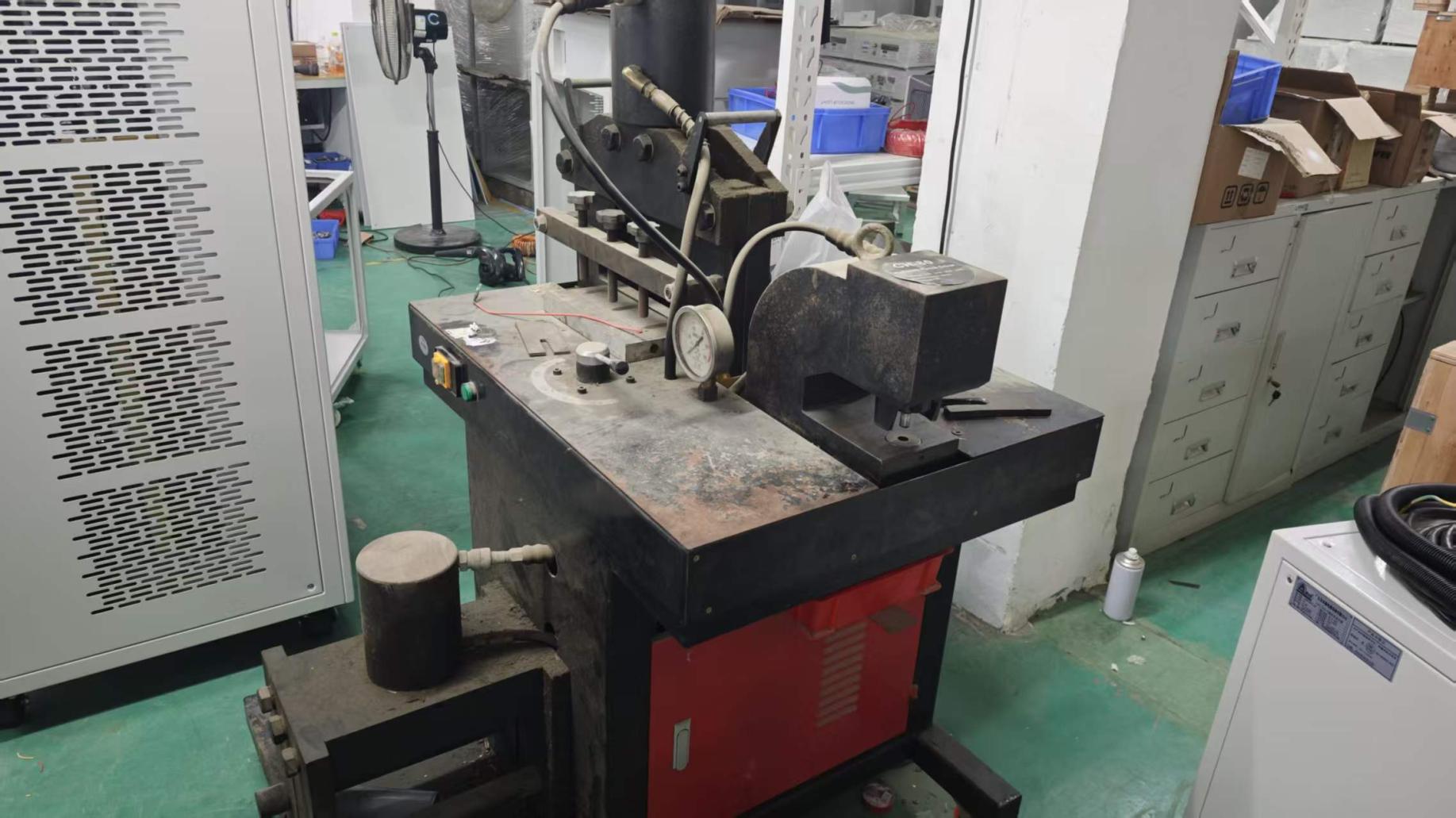
Precision power supplies require structural resilience. In an industrial surface finishing plant, vibration from agitation pumps and chemical exposure can damage fragile frames. Fenvix produces its own heavy-gauge cabinet enclosures using dedicated plate shearing machines, punching presses, precision milling equipment, and automatic tapping stations. This ensures high dimensional accuracy, superior thermal ducting airflow, and corrosion-resistant powder coatings.

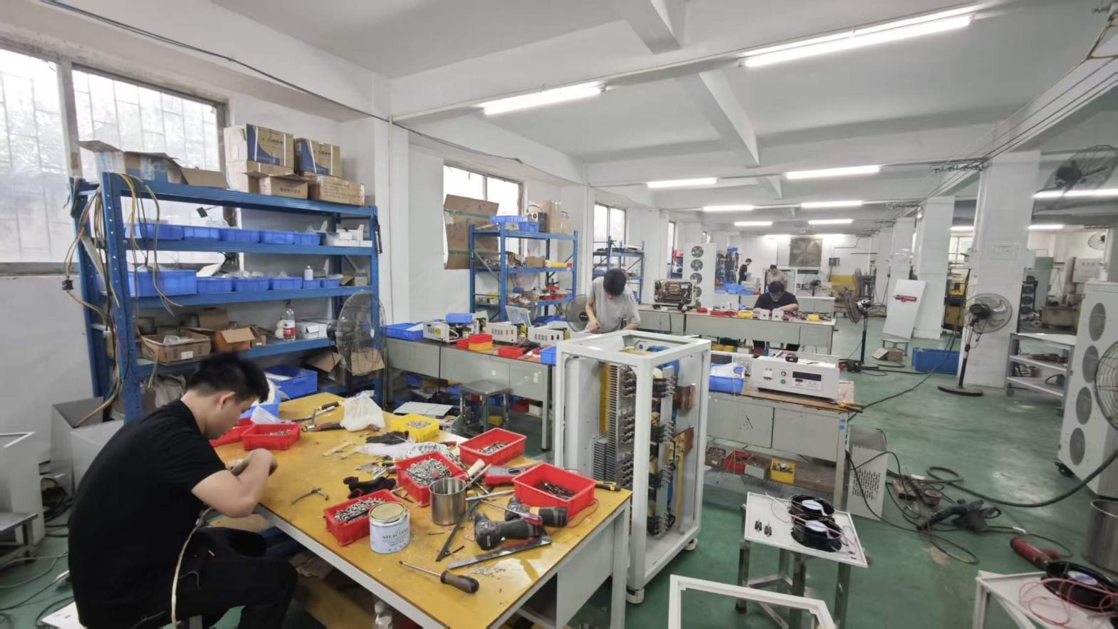
Fenvix Modern Workshop
3,000m² Production Facility Clean, organized assembly line for industrial power systems.
Finished Rectifier Line
Finished Rectifier Cabinets Burn-in ready cabinets ready for global dispatch.
Assembly Process 1
Assembly Process 1 Internal power module mounting and busbar routing.
Assembly Process 2
Assembly Process 2 Precision wiring, wire bundling, and optical insulation.
Assembly Process 3
Assembly Process 3 Logic control board installation and front panel fitting.
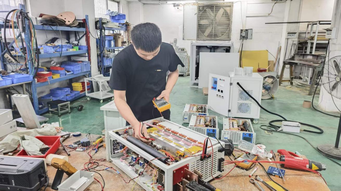
Commissioning
Power Commissioning Pre-shipment functional testing and parameter calibration.
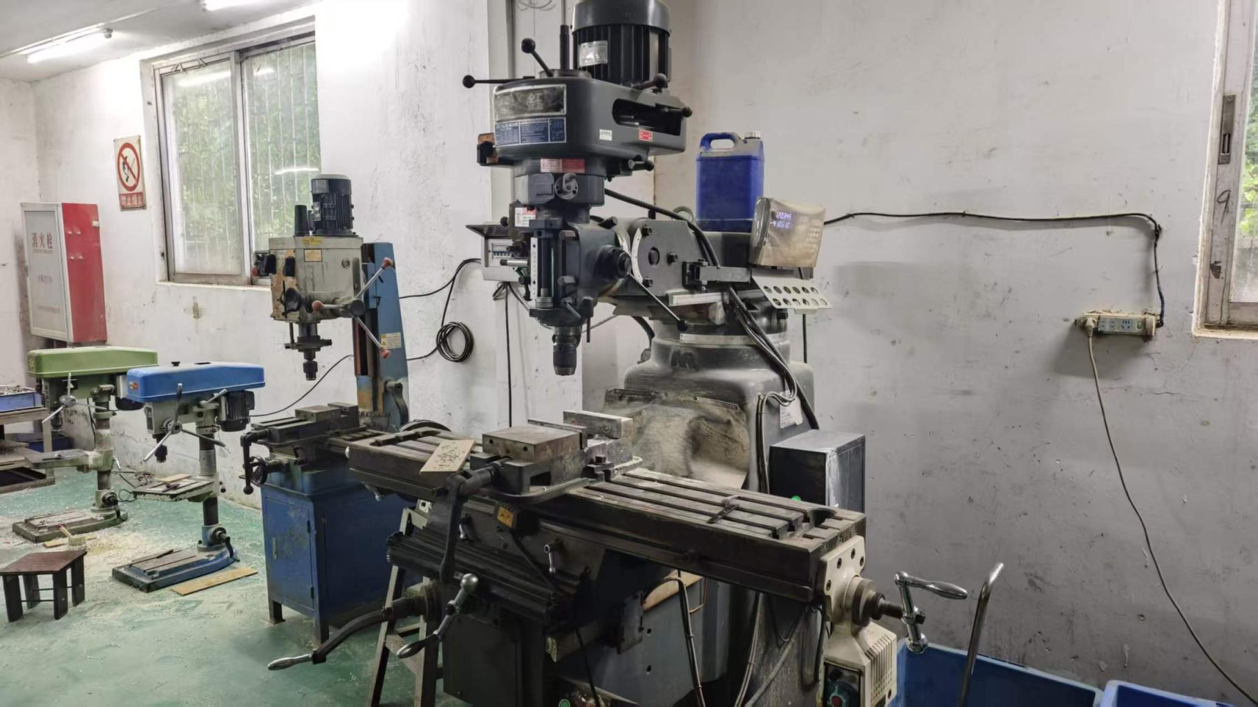
Milling Machine
Milling Machine In-house machining of copper heatsinks and busbars.
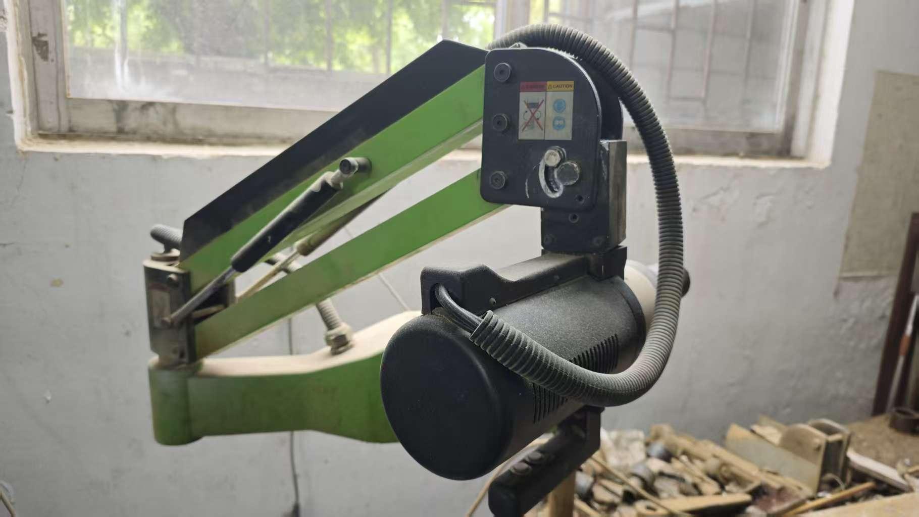
Tapping Machine
Tapping Machine Precise mechanical threads for secure electrical joints.
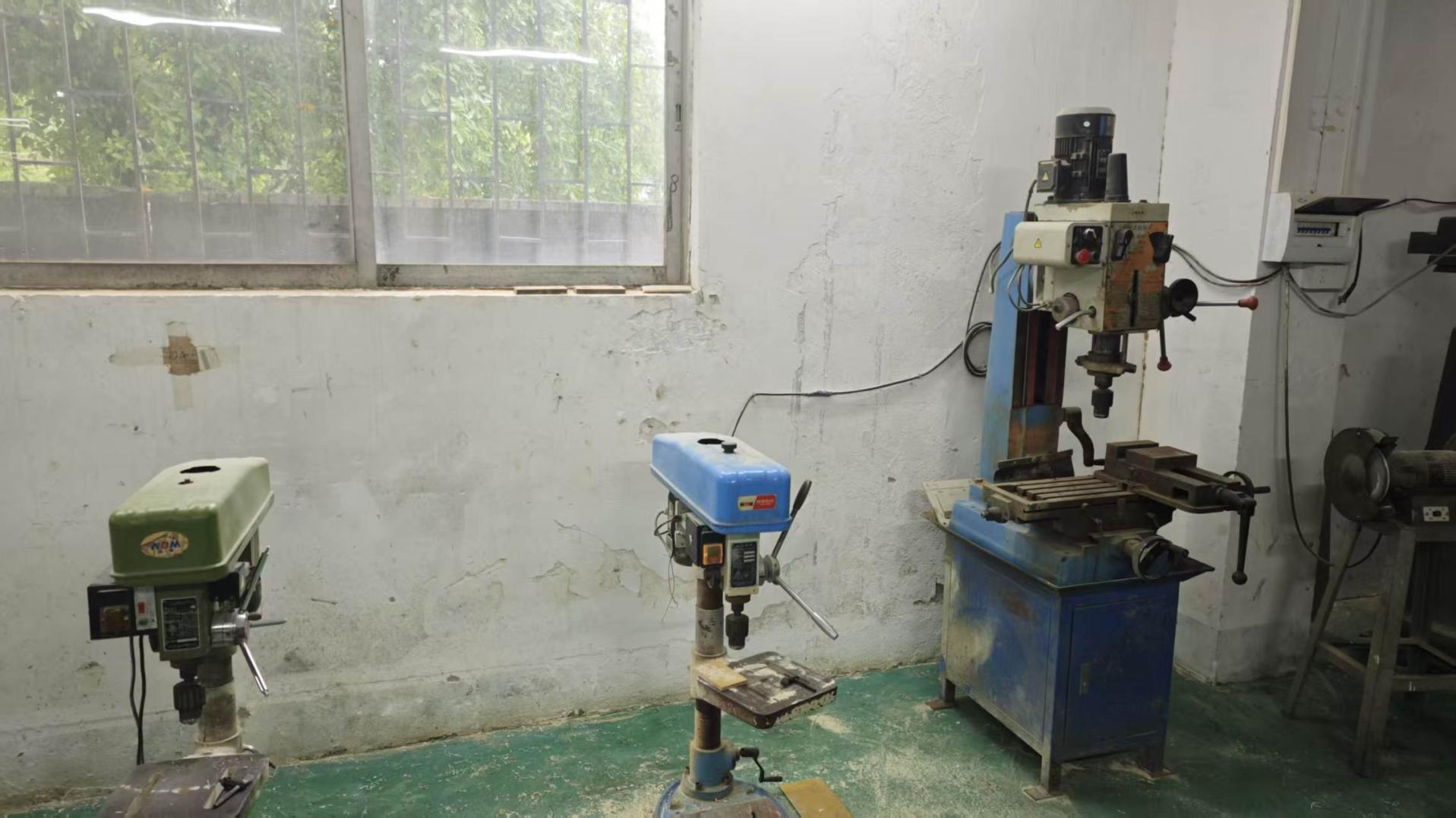
Drilling Machine
Drilling Machine Heavy structural drilling for busbars and brackets.
Plate Shearing Machine
Plate Shearing Machine Heavy-gauge enclosure steel cutting under exact tolerances.
Punching Machine
Punching Machine Perforation of ventilation louvers and panel knockouts.
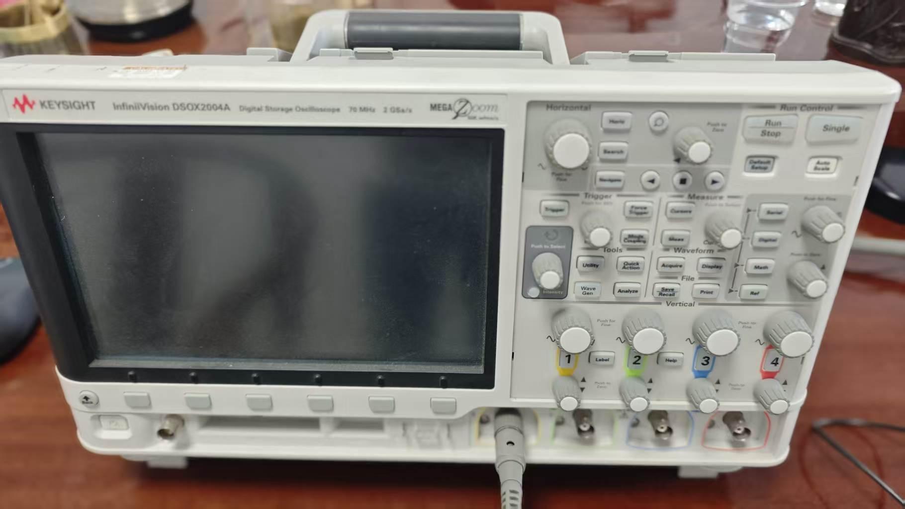
Oscilloscope Quality Testing
Oscilloscope Testing Rigorous waveform analysis, ripple verification & transient check.

E-E-A-T Quality Commitment: Experience, Expertise, Authoritativeness & Trust

Every electrophoresis paint power supply that exits our Guangdong plant represents thousands of hours of field-tested engineering:

  • Experience (13+ Years): We have solved challenging application quirks across more than 50 distinct coating formulations, including cathode sludge reduction, hollow tube throwing power enhancement, and low-temperature e-coat curing support.
  • Expertise: Our core R&D team consists of power electronics engineers with deep domain expertise in switch-mode resonant power conversion, digital signal processing (DSP), and thermodynamic modeling.
  • Authoritativeness: Verified on-site by TÜV Rheinland and holding ISO 9001, CE, EMC, and RoHS certifications, Fenvix products are deployed across Europe, North America, Southeast Asia, and the Middle East.
  • Reliability: We enforce incoming inspection (IQC) for all semiconductors (using genuine Infineon, Fuji, or Semikron modules), in-process inspection (IPQC) throughout metalworking and wiring, and mandatory 100% burn-in load testing (FQC) verified by high-speed digital oscilloscopes.

Need a Tailored Electrophoresis Paint Power Supply Solution?

Send your tank dimensions, line throughput, and paint specifications to Guangdong Fenvix Technology Co., Ltd. Our engineering team provides schematic recommendations and factory quotations within 24 hours.

[email protected]