[email protected]
ISO 9001 Certified Manufacturer Exporting to 4 Continents
Global Procurement & Engineering Whitepaper

How to Select, Scale, and Integrate a Capacitor Charging High Voltage Power Supply for Extreme Pulsed Power, High Repetition Rates, and Harsh Industrial Environments?

An authoritative engineering and procurement assessment exploring LC series-parallel resonant topologies, arc-quenching dynamics, joule-per-second scaling rules, and life-cycle risk mitigation for pulsed lasers, plasma physics, and medical modulators.

Get Catalog Consult Power Engineers
Technical Fundamentals

Deconstructing the Capacitor Charging High Voltage Power Supply

In advanced pulsed power engineering, standard constant-voltage (CV) regulated DC sources inevitably fail when directly coupled to capacitive loads. At the onset of charging, an uncharged capacitor acts precisely as a short-circuit ($V_C = 0$). Standard DC switch-mode supplies experience severe current spikes, enter continuous thermal foldback, or trigger destructive shoot-through failures in primary semiconductor switches.

A specialized Capacitor Charging High Voltage Power Supply (CC-HVPS) is specifically engineered to operate unconditionally as a true constant-current source throughout the charging ramp. Using series resonant inverter topologies (such as LLC or LC series-parallel resonant bridges), the supply charges the load capacitance linearly: $$\frac{dV}{dt} = \frac{I_{charge}}{C}$$ This behavior ensures a flat power draw profile, predictable charging times, and negligible switching losses via Zero Voltage Switching (ZVS) or Zero Current Switching (ZCS) transitions. As industrial accelerators, pulsed TEA carbon dioxide lasers, flashlamp pumped Nd:YAG lasers, and electromagnetic forming tools demand faster repetition rates (100 Hz to over 5 kHz), the power supply must transition between zero-load and short-circuit conditions millions of times without thermal drift.

Core Architectural Equation: Energy stored in the capacitive bank equals $E = \frac{1}{2} C V^2$. The charging rate required from the power source is calculated by: $$P_{peak} = C \cdot V_{peak} \cdot \left(\frac{dV}{dt}\right) = 2 \cdot P_{average}$$ Procurement teams must therefore distinguish clearly between the nominal continuous average power (in kW) and the peak charging rate expressed in Joules per second (kJ/s).
Dynamic Stability

The Physics of Arc-Quenching & Reverse Energy Protection

When powering high-voltage plasma discharge chambers, gas-discharge switches, or pulse-forming networks (PFN), instantaneous load breakdowns and dielectric flashovers are operational certainties. In a hard spark gap breakdown or laser self-flash, the capacitor voltage collapses to zero in nanoseconds. The reflected wave transmits massive negative transient voltage spikes directly back into the secondary output stage of the capacitor charging high voltage power supply.

Guangdong Fenvix Technology Co., Ltd. integrates a comprehensive three-stage anti-reflex network consisting of ultrafast high-voltage series damping assemblies, surge-rated avalanche diodes, and fast crowbar circuits. Our control loop senses collapse within <10 microseconds, actively blanking PWM drive pulses to prevent transformer saturation. Once the load arc de-ionizes, the supply resumes linear charging without latching off, ensuring continuous operation on automated production lines.

Typical Failure Points in Commercial Power Supplies:

  • Dielectric tracking across transformer windings during repetitive dv/dt stress.
  • High-voltage diode matrix avalanche breakdown caused by undamped reflected ringing.
  • Control loop overshoot causing overvoltage breakdown on delicate capacitor dielectric foils.
  • Corona degradation inside high-density potting encapsulants.
Product Recommendations

Engineered Capacitor Charging High Voltage Power Supply Solutions

Field-proven topologies configured for precision laboratory modulators, high-voltage flashlamps, pulse-forming networks, and industrial continuous-duty manufacturing.

0-100kV Ultra HV 0-100kV capacitor charging high voltage power supply

0–100kV Precision Capacitor Charging & Discharging Supply

  • Charging Voltage0–100kV Continuous
  • Peak Energy Rate1kJ/s – 10kJ/s Custom
  • RepeatabilityBetter than 0.1%
  • InterfaceIsolated Analog & RS485
MOQ: 1 Set (Fully Customizable)
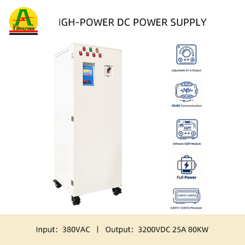
3200V / 80kW Pulse 80kW 3200V high voltage capacitor charging power supply

80kW 3200V High-Power Fast Rep-Rate Charger

  • Voltage Spectrum1000V / 2000V / 3200V
  • Average Power80kW Continuous
  • Cooling TopologyDeionized Liquid Cooled
  • ProtectionMulti-Stage Arc Quench
MOQ: 1 Set
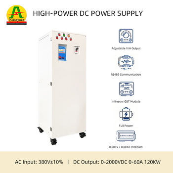
120kW Dynamic 120kW programmable high voltage capacitor charger

120kW 2000V High-Energy Modulator Supply

  • Voltage Range0–2000V Adjustable
  • Current Capability0–60A Constant Current
  • RegulationDual DSP Digital Control
  • Target LoadMarx Banks & PFNs
MOQ: 1 Set
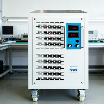
Compact Bench 16kW 0-4000V high voltage capacitor power supply

16kW 4000V High Repetition Capacitor Charger

  • Voltage Setting0–4000V Step-Adjustable
  • Charging RateUp to 16,000 J/s
  • Efficiency≥ 92% at Full Load
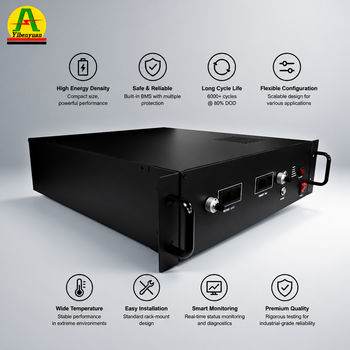
  • Dimensions19-Inch Rack Mount
MOQ: 1 Unit
Request Full Specifications & Custom Sizing
Industry Insight

Strategic Procurement & Technology Trends in Capacitor Charging Systems

How the convergence of wide-bandgap silicon carbide (SiC), AI-assisted predictive diagnostics, and distributed energy architectures is transforming industrial high-voltage purchasing.

1. Silicon Carbide (SiC) Resonant Topologies

Traditional high-voltage capacitor charging power supplies relied heavily on silicon IGBT modules switched at frequencies between 20 kHz and 45 kHz. The market is shifting decisively toward Silicon Carbide (SiC) MOSFET-based high-frequency resonant inverters operating above 100 kHz. This eliminates audible switching noise, slashes magnetic core volume by 60%, and drastically reduces internal stored reactive energy—mitigating explosion hazards during load breakdowns.

2. High Pulse Repetition Rates (>1 kHz)

Next-generation industrial applications—such as extreme ultraviolet (EUV) light sources, pulsed excimer lithography, medical lithotripsy, and continuous non-thermal food sterilization—demand charging cycles repeating hundreds to thousands of times per second. Power supply buyers now scrutinize the "dead-time de-inversion window," requiring programmable post-discharge holdoffs so switches can clear before recharging begins.

3. Digital Twins & Real-Time Telemetry

Modern procurement contracts require edge-computing industrial communication protocols (EtherCAT, Profinet, Modbus-TCP) alongside traditional optically isolated BNC trigger lines. Remote monitoring of peak charging currents, inter-pulse voltage jitter, oil dielectric breakdown temperatures, and resonant tank phase margin enables predictive maintenance before insulation failure occurs in continuous manufacturing lines.

Future Procurement Criteria Checklist for Senior Engineers

When formulating requests for proposals (RFPs) for capital pulsed-power equipment over the next 5 to 10 years, technical procurement specialists must mandate:

  • Shot-to-Shot Repeatability: Ensuring the final capacitor voltage stays within ±0.05% of setpoint regardless of utility grid brownouts or input voltage ripple.
  • Harmonic Distortion and Power Factor: Integrated Active Power Factor Correction (APFC) achieving PF > 0.98 to comply with IEEE 519 standards and eliminate harmonic interference on sensitive sensor channels.
  • Modular Parallel Scalability: Multi-cabinet master-slave architectures allowing systems to scale from 30kJ/s to 300kJ/s without re-engineering the primary control subsystem.
  • Encapsulation Reliability: Vacuum-degassed silicone or dry transformer epoxy dielectric systems avoiding toxic sulfur hexafluoride (SF6) gas or mineral oil leaks.
Selection Guide

Technical Comparison Matrix: Capacitor Charging vs Standard DC Sources

Understand the critical operational boundaries between continuous DC power supplies and specialized capacitor charging architectures.

Performance Attribute Conventional DC Power Supply Fenvix Capacitor Charging HV Power Supply Procurement Impact
Short-Circuit Response ($V_C=0$) Enters current foldback or triggers thermal overload shutdown True linear constant-current charging from zero volts Prevents unexpected system interlock tripping every charge cycle
Peak-to-Average Power Ratio Rated purely for continuous steady-state wattage ($P_{cont}$) Designed specifically for $P_{peak} = 2 \cdot P_{avg}$ rating Eliminates the need to over-specify supply rating by 200–300%
Repetition Rate Handling Limited to slow ramps (<0.5 Hz); output caps overheat Engineered for 1 Hz up to 5,000 Hz continuous pulse rates Enables high-throughput industrial and medical laser systems
Stored Output Filter Energy High output capacitance ($C_{out}$) required to smooth DC ripple Ultra-low internal output capacitance to prevent flash dumping Protects load chambers and spark switches from destructive energy dumps
Load Arc Reflectance Resistance Reflected high-voltage transients destroy the bridge rectifier 3-Stage ultrafast snubber, reverse diode, and crowbar clamp Guarantees 24/7 reliability in unpredictable plasma discharge regimes
Voltage Regulation Accuracy Continuous analog/digital feedback loop ($0.5\% - 1.0\%$) High-speed sample-and-hold comparator loop (<0.05% jitter) Provides high pulse-to-pulse optical and physical consistency
Enterprise Strengths & Production Capability

Precision Manufacturing by Guangdong Fenvix Technology Co., Ltd.

Combining heavy-duty sheet-metal fabrication, advanced high-voltage winding, and meticulous multi-stage quality assurance under an ISO 9001 certified framework.

In-House Tooling, Fabrication & Total Process Control

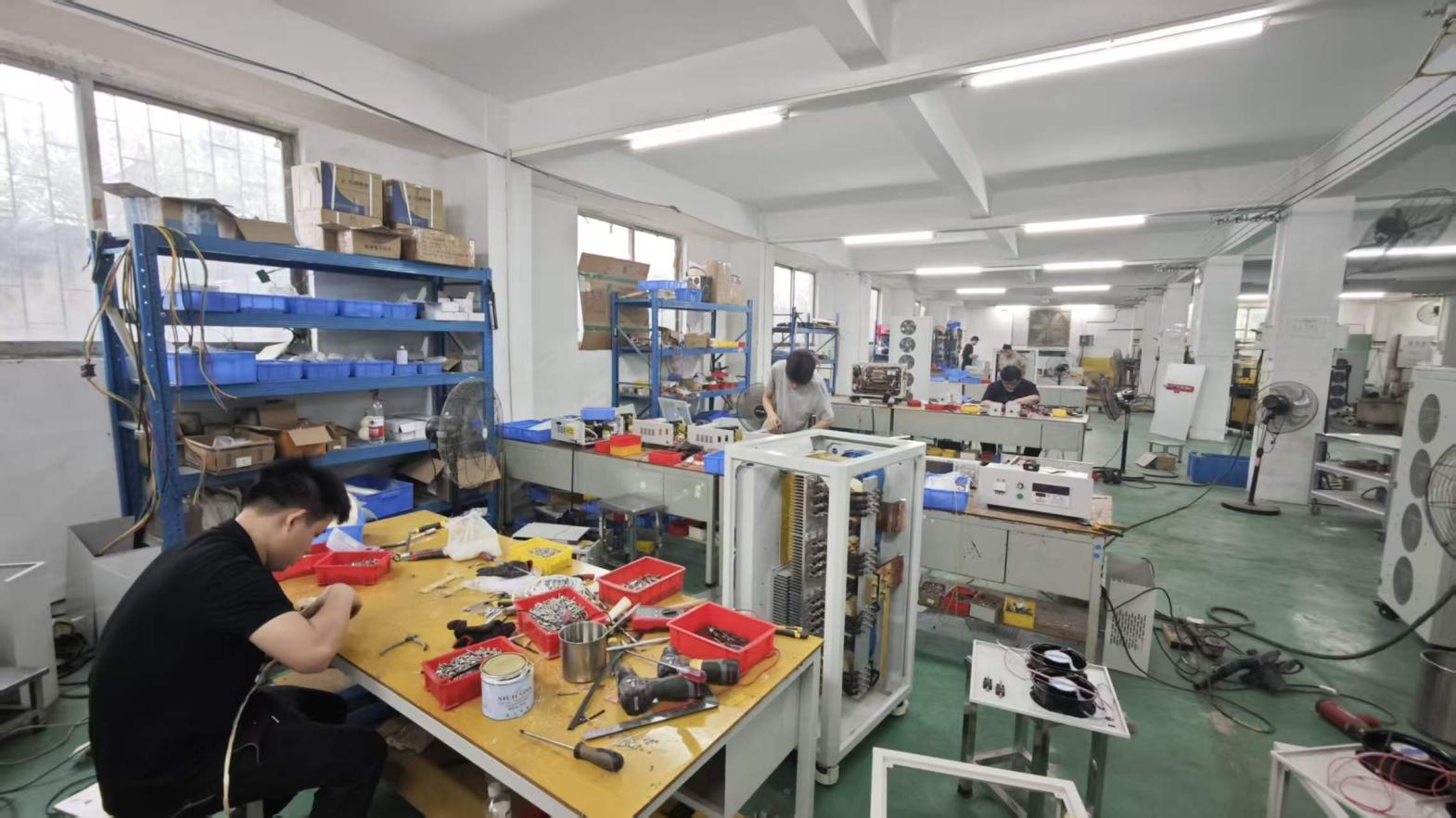
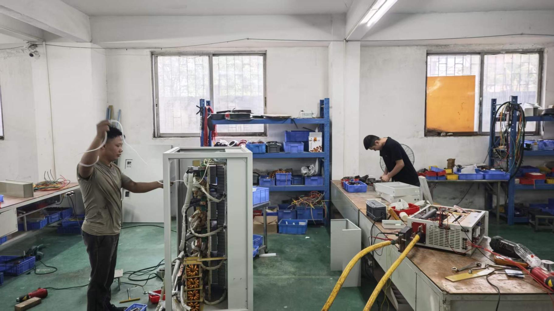
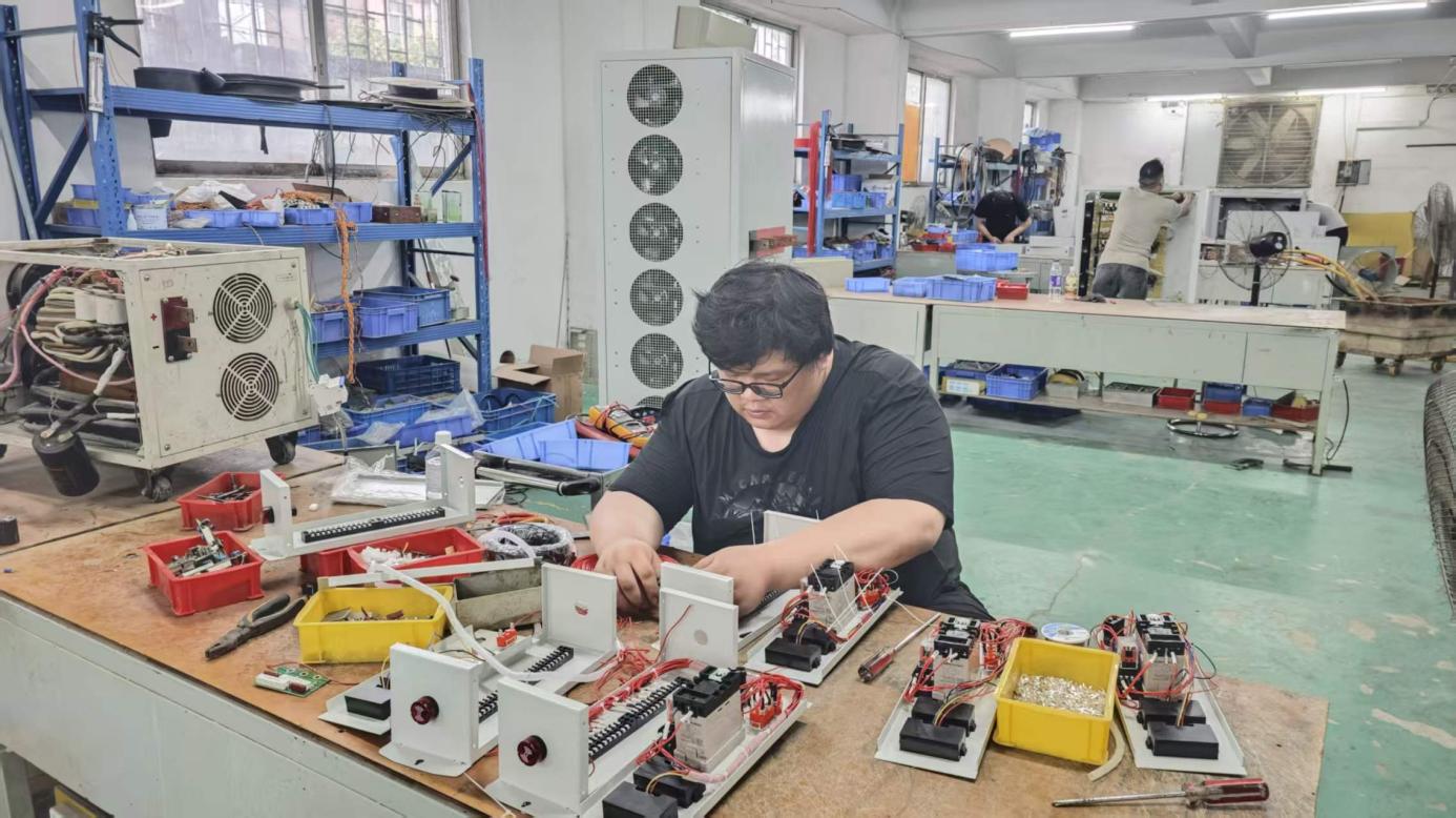
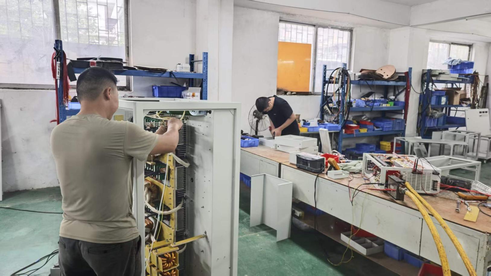
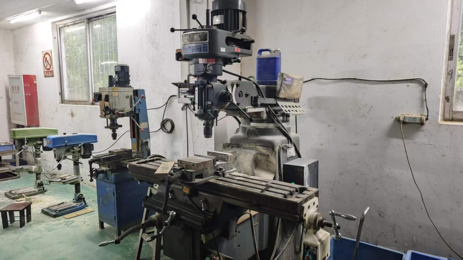
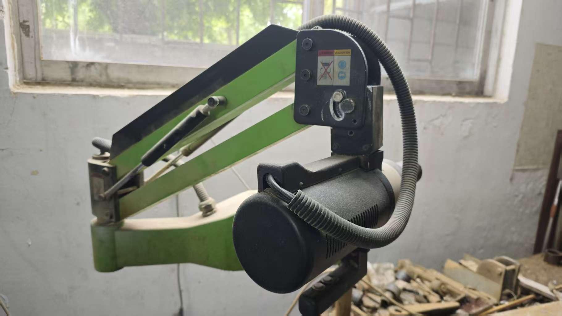
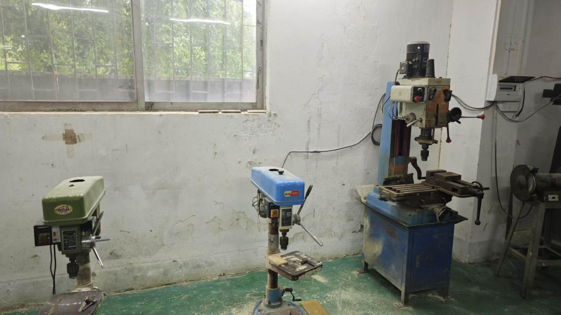
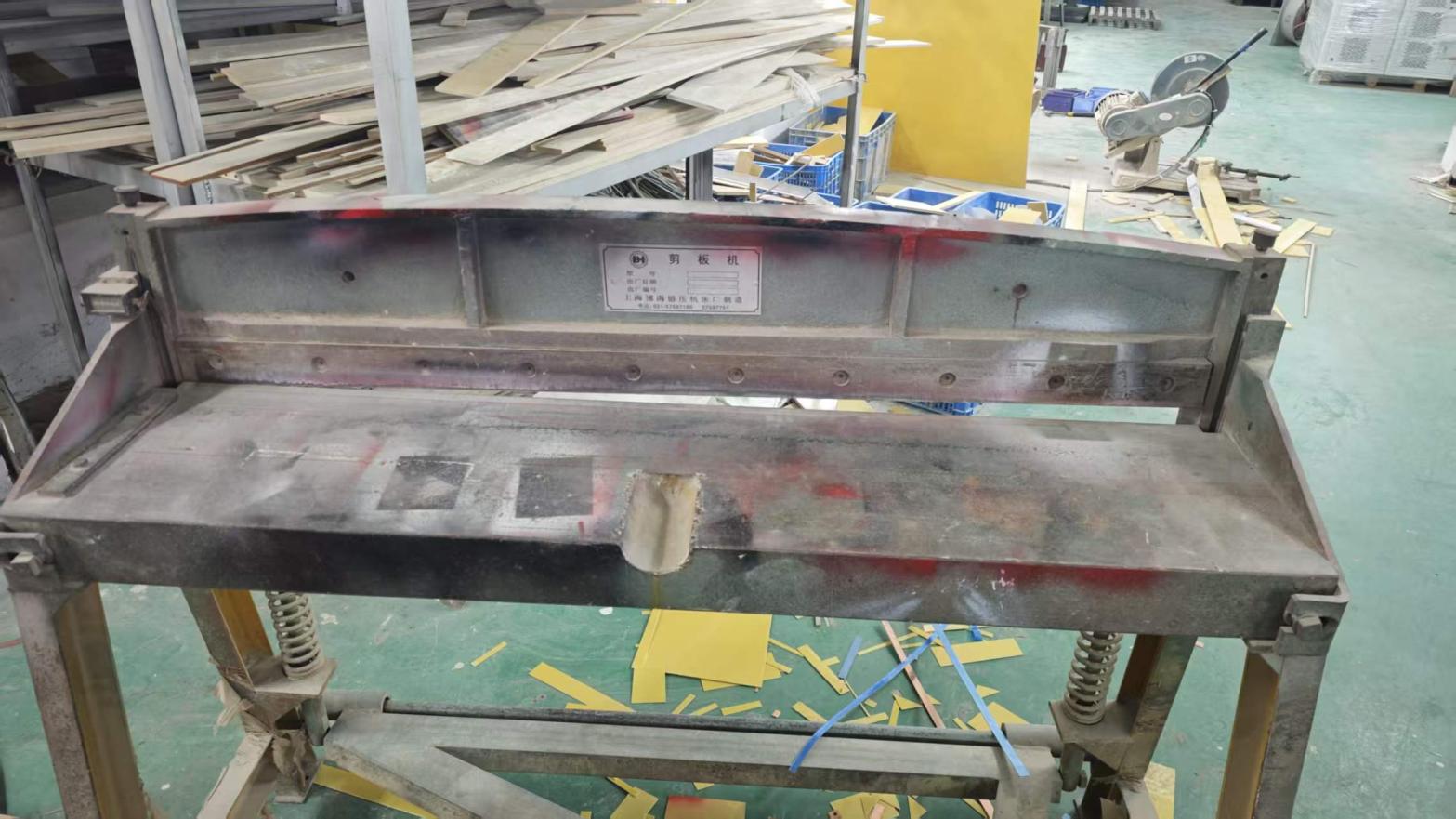
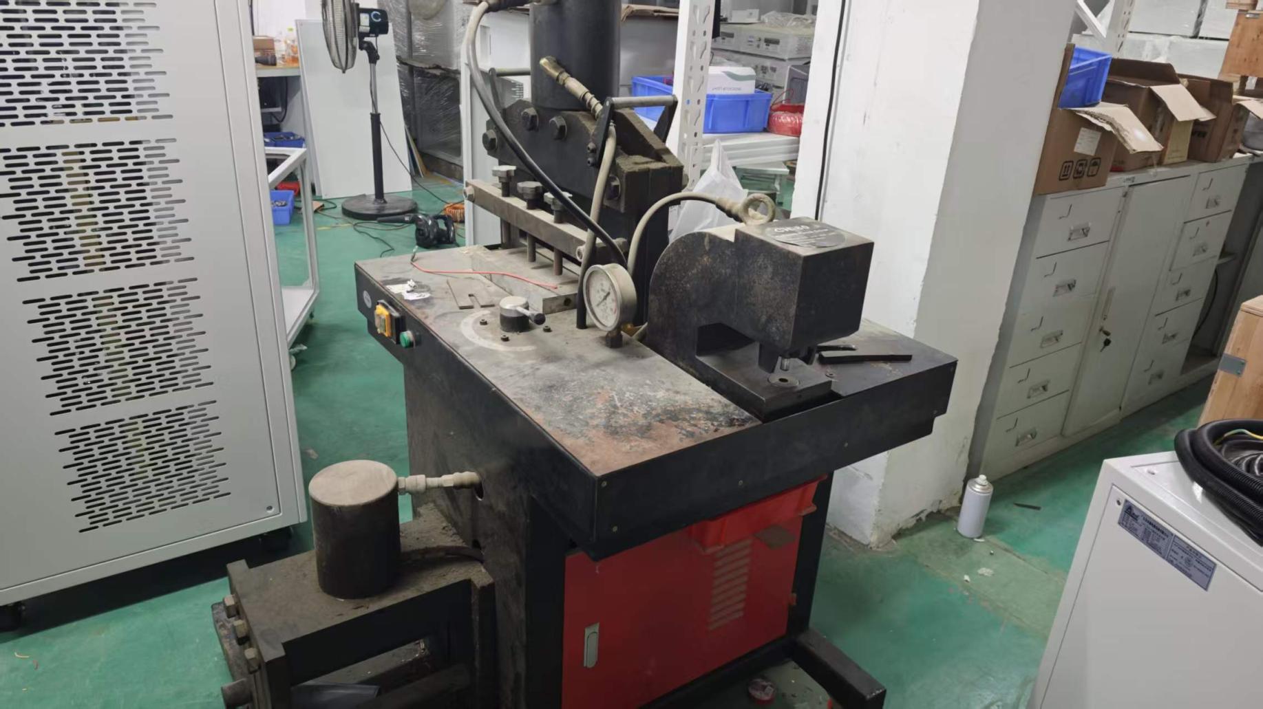
Founded in 2013, Guangdong Fenvix Technology Co., Ltd. does not outsource cabinet fabrication, internal structural frames, or custom copper busbars to third-party workshops. Our 3,000 m² manufacturing floor in Guangdong features dedicated plate shearing, CNC punching, milling, drilling, and tapping infrastructure. This enables us to build custom high-voltage chassis, anti-tracking dielectric barriers, and optimized forced-air or liquid cooling manifolds with sub-millimeter precision.

By eliminating external sheet metal lead times, we fast-track custom engineering cycles, producing turn-key prototypes within 3 to 4 weeks while maintaining strict compliance with creepage and clearance distances mandated by IEC 61010-1 and UL 508.

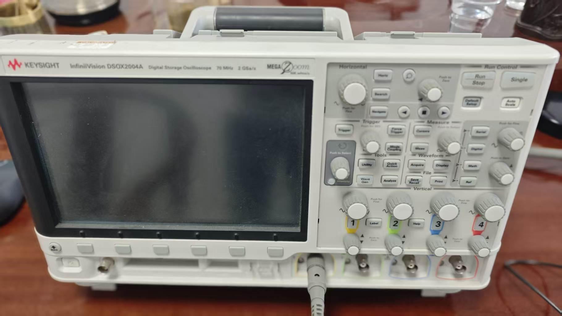
Rigorous Testing: Oscilloscopes, Partial Discharge & Burn-In

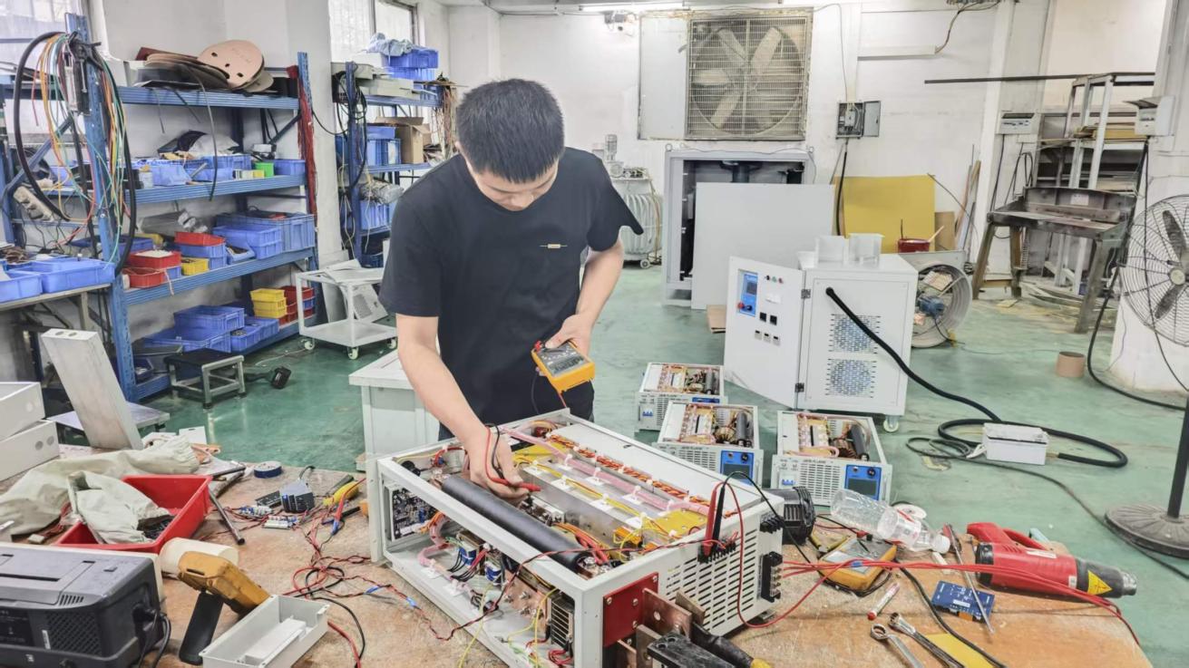
Every capacitor charging high voltage power supply manufactured in our facility undergoes rigorous multi-point validation before dispatch. We do not rely merely on static resistive bank tests; every charger is coupled to high-frequency capacitive pulse networks and evaluated under forced breakdown conditions.

Using high-bandwidth digital storage oscilloscopes, active high-voltage probes, and thermal imaging cameras, our engineering team measures:
• Real-time current ramping linearity and transition ripple.
• Turn-off deadband jitter and pulse-to-pulse voltage stability.
• Thermal equilibrium profiles under continuous full-rep-rate burn-in.
• High-voltage insulation integrity under ambient humidity stress.

Global Compliance & Credibility

Verified Manufacturing Credentials & Standards

Engineered to international high-voltage, electromagnetic, and electrical safety standards for effortless multi-regional regulatory compliance.

ISO 9001:2015

Certified quality management across design and high-voltage manufacturing

CE Compliance

Full conformance with European LVD (2014/35/EU) and EMC (2014/30/EU)

TÜV On-Site Verified

Independent third-party production capability audit and certification

Worldwide Logistics

Engineered shock-isolated export crating; CIF, DDP, and FOB terms

Direct Engineering Support

Direct communication with high-voltage design team; no broker delays

Flexible OEM/ODM

Custom form factors, specific voltages, and proprietary communication protocols

Procurement FAQ

Frequently Asked Questions on Capacitor Charging HV Power Supplies

Critical engineering considerations, calculations, and operational parameters answered directly by our high-voltage technical specialists.

How do I accurately calculate the required charging rate (kJ/s) for my capacitive load?
To specify the correct charging rate, calculate the energy per shot using $E = \frac{1}{2} C V^2$, where $C$ is capacitance in Farads and $V$ is target peak voltage in Volts. The charging rate is then defined by: $$P_{charge} = \frac{E}{t_{charge}} = \frac{\frac{1}{2} C V^2}{t_{charge}}$$ If operating in a repetitive pulsed regime at frequency $f$ (Hz), the required continuous charging power is: $$P_{charge} = \frac{1}{2} C V^2 \cdot f$$ Always account for the deadband/discharge recovery time $t_d$ (the brief window where the capacitor discharges and the switch recovers). The effective charging time becomes $t_{charge} = \frac{1}{f} - t_d$. Engineers at Guangdong Fenvix Technology Co., Ltd. recommend adding a 15–20% safety margin to ensure reliable thermal headroom.
Why must a resonant converter topology be used instead of a standard hard-switched PWM converter?
Standard hard-switched pulse-width-modulated (PWM) converters suffer excessive capacitive turn-on switching losses when cycling down to zero volts. A Series Resonant Inverter (SRI) or LLC topology provides intrinsic Zero Current Switching (ZCS) or Zero Voltage Switching (ZVS) throughout the charging cycle. The leakage inductance of the high-voltage step-up transformer is merged directly into the resonant circuit tank, transforming parasitic transformer capacitance from a source of destructive ringing into an active energy-transfer element. This maximizes electrical efficiency (≥90%), minimizes EMI emissions, and prevents thermal degradation of IGBT/SiC modules.
What protections are provided against repetitive flashovers, load breakdowns, and arc discharges?
Guangdong Fenvix Technology Co., Ltd. incorporates an integrated 4-tier protection architecture:
1. Ultrafast Overcurrent Trip: Hardware comparators shut down drive pulses in <10 μs when secondary current exceeds 120% of rated peak.
2. Reverse Energy Suppression: High-voltage transient suppression networks and series avalanche clamping assemblies absorb the negative inductive ringing generated during spark gaps or laser breakdowns.
3. Anti-Arc Blanking: Following a breakdown event, the internal controller pauses energy delivery for an adjustable 1–10 ms window to allow plasma de-ionization before automatically resuming linear charging.
4. Thermal Interlocks: Multi-sensor thermal cutouts monitor high-voltage transformer cores, primary silicon heatsinks, and liquid cooling return lines.
Can multiple capacitor charging high voltage power supplies be paralleled for higher power?
Yes. We support master-slave parallel configurations where a designated master unit receives high-level commands via RS485, CAN bus, or analog controls, and synchronizes slave units through high-speed digital fiber-optic links or isolated gate sync lines. This parallel topology balances current within ±2% across multiple 30kW or 80kW cabinets, allowing scalable mega-joule pulse power systems without ground loop interference or control instability.
What is the typical lead time and minimum order quantity (MOQ) for custom configurations?
Guangdong Fenvix Technology Co., Ltd. operates with a strict No Minimum Order Quantity (MOQ = 1 unit) policy. We actively support research prototypes, specialized laboratory test benches, and pre-production military/medical qualification units. Standard configured models ship within 2 to 3 weeks, while fully custom, high-voltage liquid-cooled architectures typically require 4 to 6 weeks from technical sign-off to full factory burn-in completion.
How does Fenvix support overseas commissioning and integration into existing PLC systems?
We provide comprehensive schematics, 3D CAD step files for enclosure planning, and detailed register maps for Modbus-RTU, Modbus-TCP, and isolated analog (0-10V / 4-20mA) interfaces. Our senior electrical engineering team provides live technical consultation, digital oscilloscope trace reviews, and remote commissioning assistance via video conferencing to guarantee seamless system integration.
Direct Factory Partnership

Ready to Configure Your High-Voltage Capacitor Charger?

Send us your required peak voltage, capacitance, pulse repetition rate, and duty cycle. Our engineers will prepare a full design evaluation and formal proposal within 24 hours.

[email protected]