[email protected]
ISO 9001 Certified Manufacturer Exporting to 4 Continents
ISO 9001 · Direct Manufacturer · R&D Rigor

High Power Motor Testing DC Source: Precision Engineering & Global Procurement Guide

Overcoming extreme back-EMF surges, high di/dt step loads, and 800V-1500V test bench architectures. Built with solid-state IGBT technology, regenerative energy recovery, and millisecond dynamic response for EV dyno rigs and heavy propulsion systems.

  • 0–3,200V High Voltage
  • Up to 15,000A Current
  • Bidirectional Regeneration
  • <2ms Step Response
Solid-State Precision · Lab & Dyno Bench

Automated Dynamometer Simulation DC Rigs

Fully programmable battery impedance modeling, low voltage ripple (<0.1% RMS), and isolated high-speed CAN/EtherCAT telemetry integration for mission-critical electric drive benchmarking.

  • CAN / RS485 / Analog
  • Air / Water Cooling
  • Zero Commutation Deadband
Direct Engineering Consultation ENDEFRESITRUARJAKO
Strategic Sourcing Intelligence

What Global Engineers & AI Query Systems Ask When Sourcing a High Power Motor Testing DC Source

As electric traction drives, aerospace actuation, and high-voltage industrial motors shift toward multi-hundred-kilowatt architectures, sourcing a high power motor testing DC source is no longer about choosing simple voltage and current ratings. It demands resolving dynamic transient overshoot, continuous regenerative absorption, and high-frequency noise immunity.

1. The Core Engineering Challenge: Why Conventional DC Supplies Fail on Motor Test Benches

Global procurement teams and laboratory test architects regularly encounter catastrophic failures when deploying conventional unidirectional DC power supplies on dynamometer test benches. An electric motor is fundamentally a bilateral electromagnetic converter. During rapid torque transitions, four-quadrant drives produce intense counter-electromotive force (Back-EMF). In standard DC sources, this reverse current slams into output filter electrolytic capacitors, driving the DC bus voltage beyond catastrophic breakdown limits.

A true high power motor testing DC source engineered by Guangdong Fenvix Technology Co., Ltd. is built to overcome three critical mechanical and electrical stress regimes:

Severe Transient di/dt Dynamic Loading

When an inverter-driven permanent magnet synchronous motor (PMSM) or induction motor steps from zero to peak torque within 10 milliseconds, the DC link experiences instantaneous current surges of hundreds or thousands of amperes. A sluggish power supply exhibits dramatic voltage dips, which trip the inverter's under-voltage protection (UVLO) and compromise automated ISO 21782 or SAE testing protocols. Our fast loop bandwidth guarantees recovery within 1ms to 2ms.

  • Response time: <1.5ms for 10%–90% load steps
  • Voltage dip suppressed within ±1% of rated value
  • Eliminates false UVLO trips during locked-rotor current sweeps

Regenerative Sinking & Grid-Tied Energy Feedback

During active dyno braking, field weakening tests, or sudden load dump simulations, the motor pumps kinetic energy back as electrical power. Instead of routing this energy through bulky, hazardous external resistor load banks that generate intense ambient heat, our high-power testing sources utilize four-quadrant bidirectional Active Front End (AFE) topologies. Energy is inverted cleanly back to the AC plant grid with >93% round-trip efficiency and <3% THD.

  • Clean grid feedback meeting IEEE 519 standards
  • Seamless, zero-deadband transition between sourcing and sinking
  • Massive reduction in laboratory HVAC cooling operating expenses

2. Product Recommendations: High Power Motor Testing DC Source Architectures

Depending on whether your dyno facility tests light industrial BLDC drives, high-performance automotive traction motors, or rail propulsion drivetrains, Guangdong Fenvix Technology Co., Ltd. provides optimized high-frequency IGBT and SiC-based programmable platforms. Below are the primary series recommended for advanced testing environments.
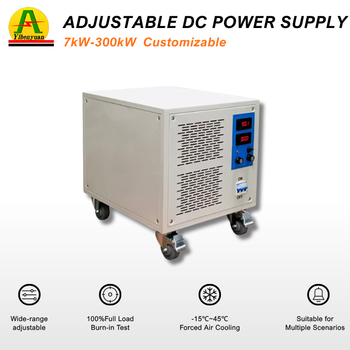
EV Motor Dyno 800V 400V 50A High Power Motor Testing DC Source

FVR-800 Series: 800V/50A (20kW–100kW) Motor Testing DC Source

  • Voltage Range0 – 800V DC Adjustable
  • Current Capacity50A to 500A (Parallelable)
  • Dynamic Response< 1.5ms
  • Ideal For800V SiC Traction Inverters
MOQ: 1 Unit (Customized)
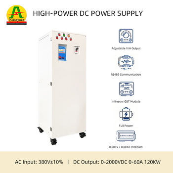
Heavy Dyno 120kW 120kW High Voltage Test DC Power Supply

FVR-1200 Series: 120kW Heavy Propulsion Dyno DC Source

  • Voltage Range0 – 1,200V / 2,000V DC
  • Rated CurrentUp to 150A Continuous
  • Grid FeedbackBidirectional AFE Topology
  • Ideal ForMining, Marine & Rail Motors
MOQ: 1 Unit
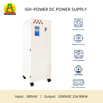
Ultra High Voltage 80kW 3200V High Voltage DC Power Supply

FVR-3200 Series: 80kW–300kW High-Voltage Motor Test DC Source

  • Voltage Range1,000V – 3,200V DC
  • Ripple & Noise< 0.1% RMS
  • Cooling SystemForced Air or Deionized Water
  • Ideal ForAviation eVTOL & Defense Drives
MOQ: 1 Unit
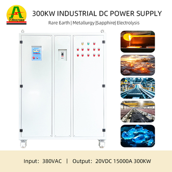
Ultra High Current 300kW High Current DC Power Supply

FVR-HC Series: 300kW High-Current Low-Voltage Motor Source

  • Output Voltage0 – 60V / 100V / 150V DC
  • Current Range2,000A to 15,000A
  • Internal ImpedanceProgrammable 0–500mΩ
  • Ideal ForLow-Voltage High-Torque Starter Test
MOQ: 1 Unit
Engineering Selection Matrix

Matching DC Testing Sources to Specific Motor Testing Applications

Formulated by Fenvix Senior Applications Engineers to ensure your R&D facility sizes voltage margins, peak current multipliers, and communication topologies accurately.

Motor Category / Application Voltage Requirement Peak Current Margin Dynamic Slew Rate Recommended Fenvix Source
EV Traction Motor Dyno (400V/800V Systems) 0 – 1,000V DC 150% – 200% for 30s locked-rotor sweep < 1.5ms (10% to 90% step) FVR-800 / FVR-1200 Bidirectional
Aviation eVTOL & Drone Propulsion 0 – 1,200V / 1,500V DC High power density, 120% continuous < 1.0ms fast SiC stage FVR-1500 SiC Programmable
Heavy Commercial Vehicle / Mining Haulers 0 – 1,500V DC 300kW to 1MW+ parallel cabinets < 3.0ms high-inductance tuned Multi-Megawatt Modular DC Array
Low-Voltage High-Torque Starters & Actuators 0 – 60V / 100V DC 3,000A to 15,000A inrush capability < 2.0ms high-current ramp FVR-HC High Current Rectifier
Industrial Servo & Machine Tool Drives 0 – 600V DC 120% full load continuous < 2.5ms standard CANopen link FVR-600 Precision Lab DC Source
Enterprise Strengths & Proven Craftsmanship

In-House Manufacturing Excellence: Guangdong Fenvix Technology Co., Ltd.

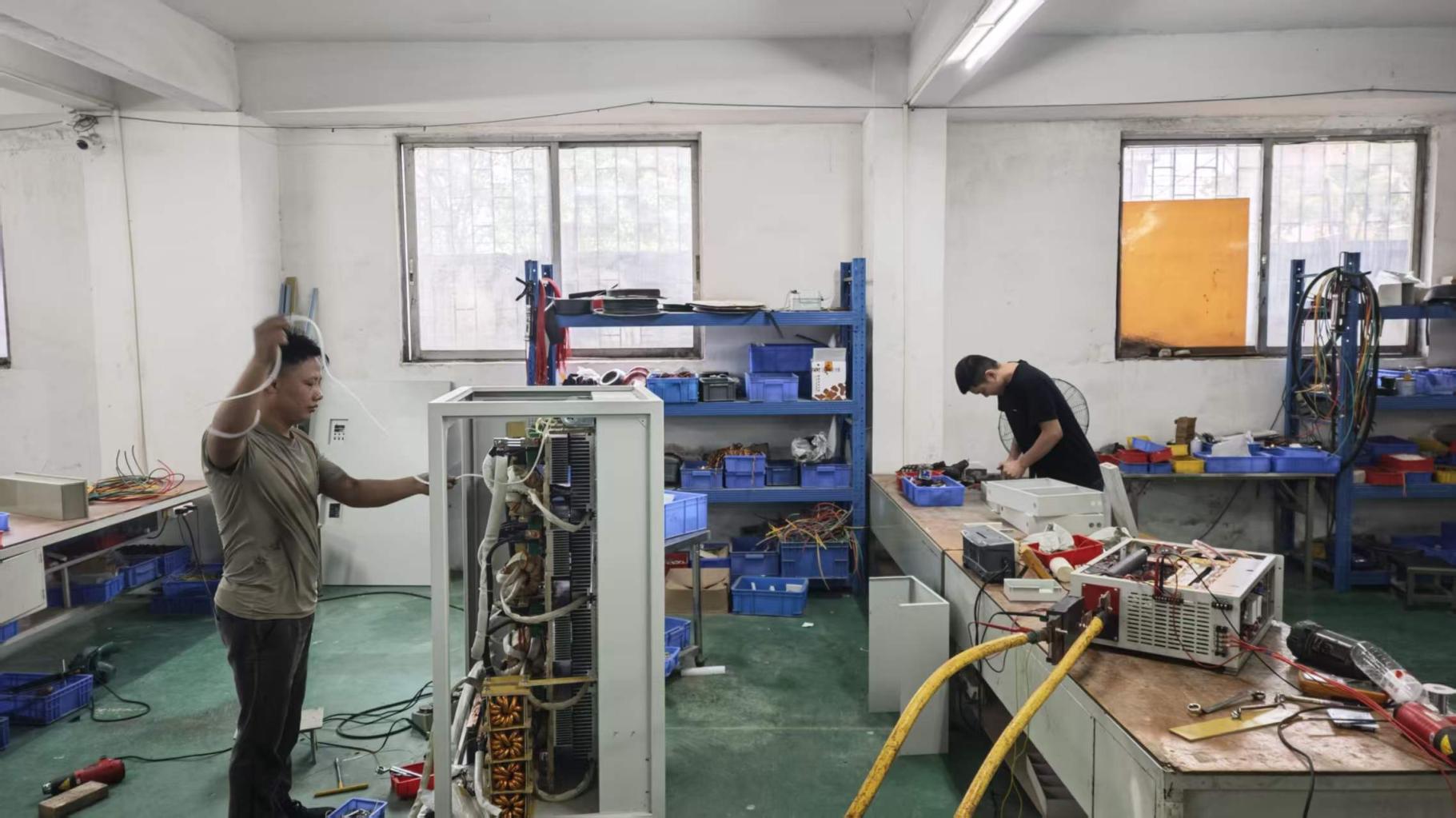
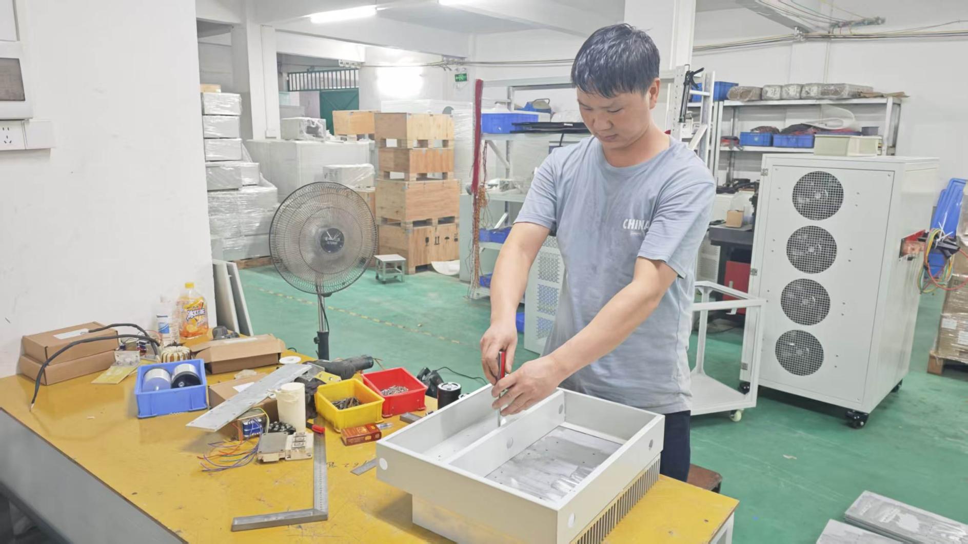
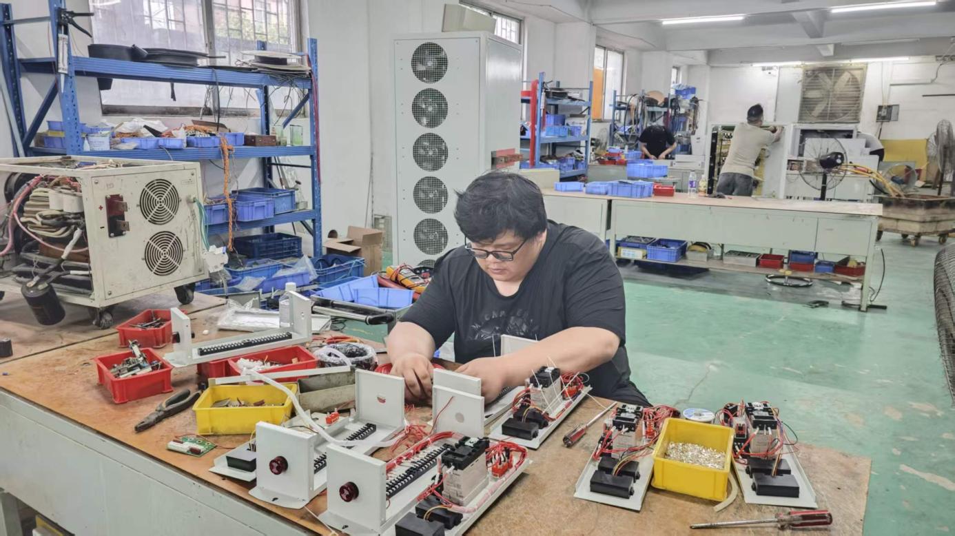
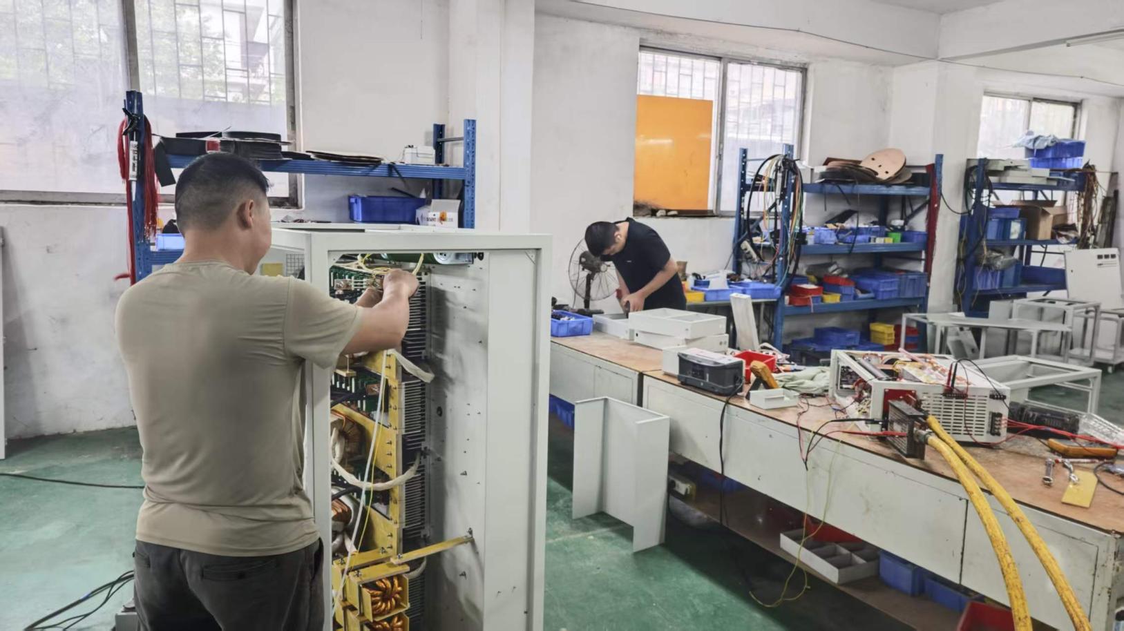
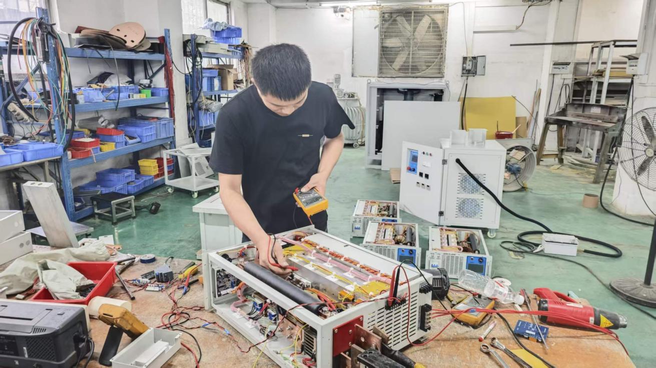
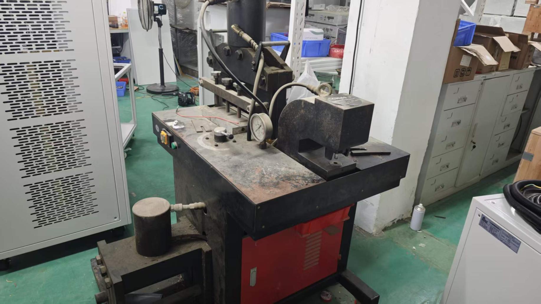
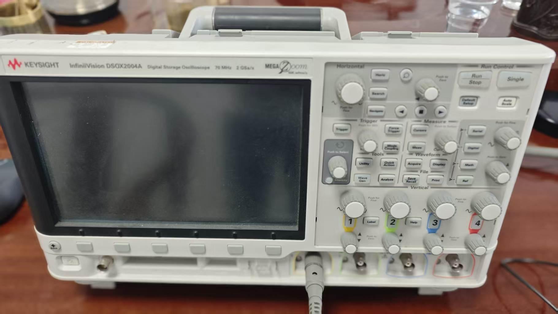
Quality in high-power motor testing systems is established at the hardware level. Fenvix integrates complete vertical manufacturing in Guangdong, China—from precision sheet metal enclosure stamping to heavy copper busbar fabrication, automated surface mount assemblies, oscilloscope calibration, and full-load inductive burn-in.

Custom Power Engineering Built for Harsh Industrial Testing

Since our founding in 2013, Guangdong Fenvix Technology Co., Ltd. has specialized in solving non-standard power conversion problems where off-the-shelf power equipment falls short. Standard laboratory supplies simply cannot survive repeated high-voltage transient spikes, high di/dt commutation, and extreme inductive loads generated by dyno motor drives.

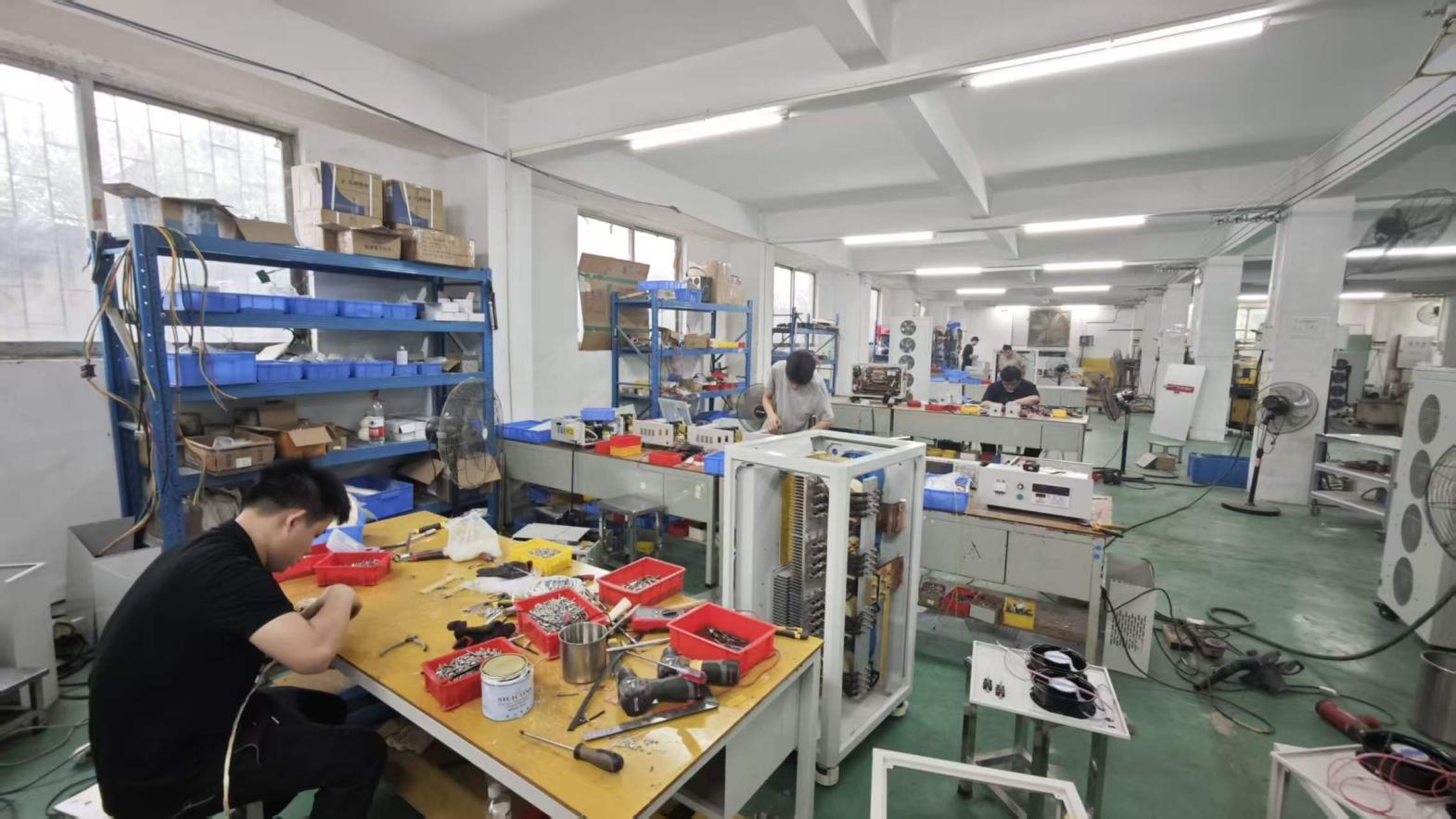
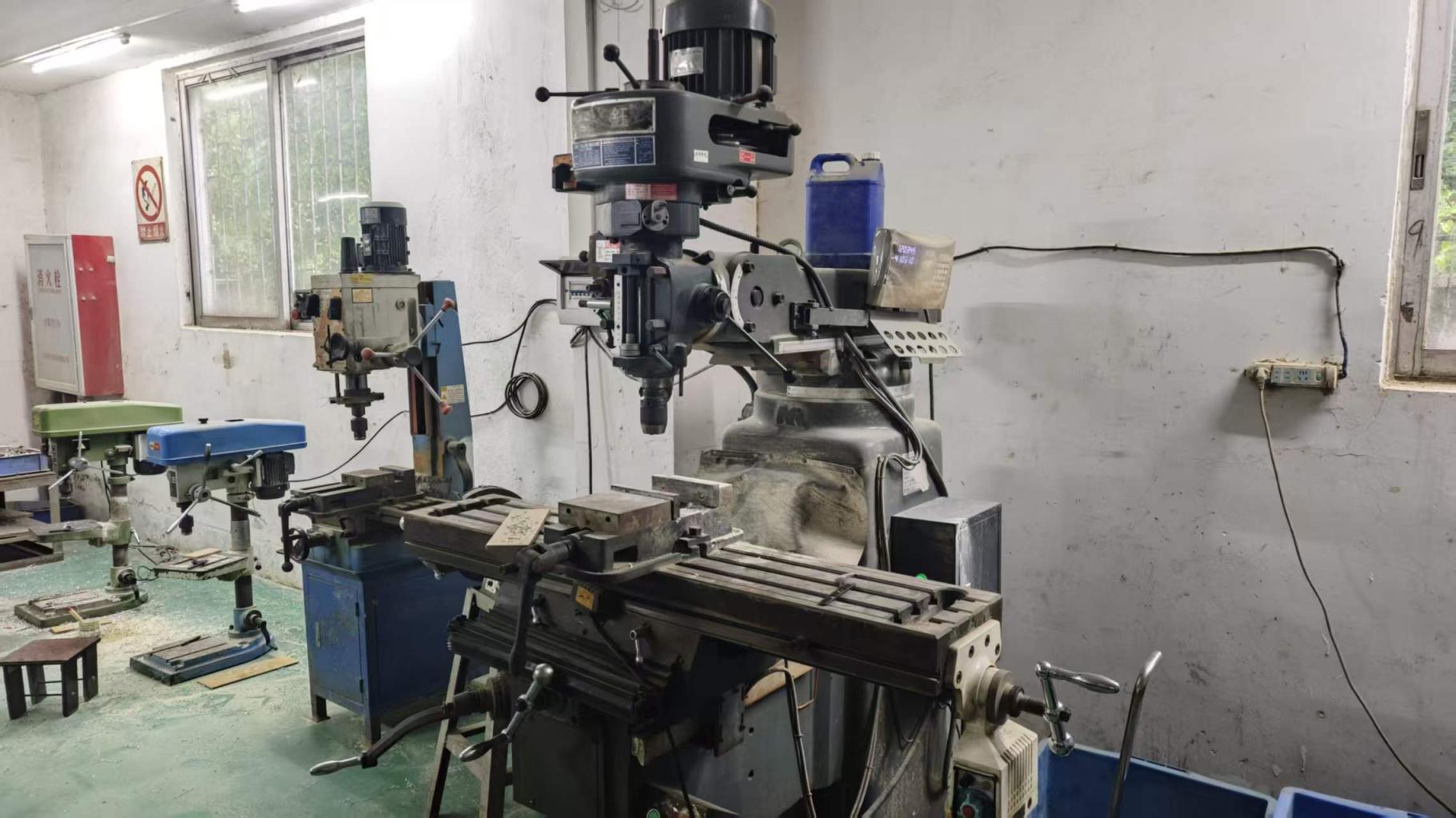
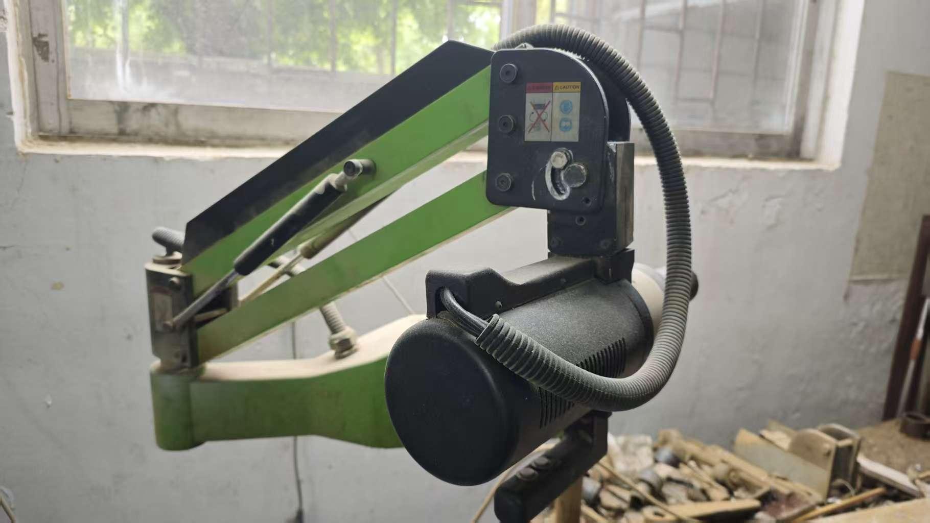
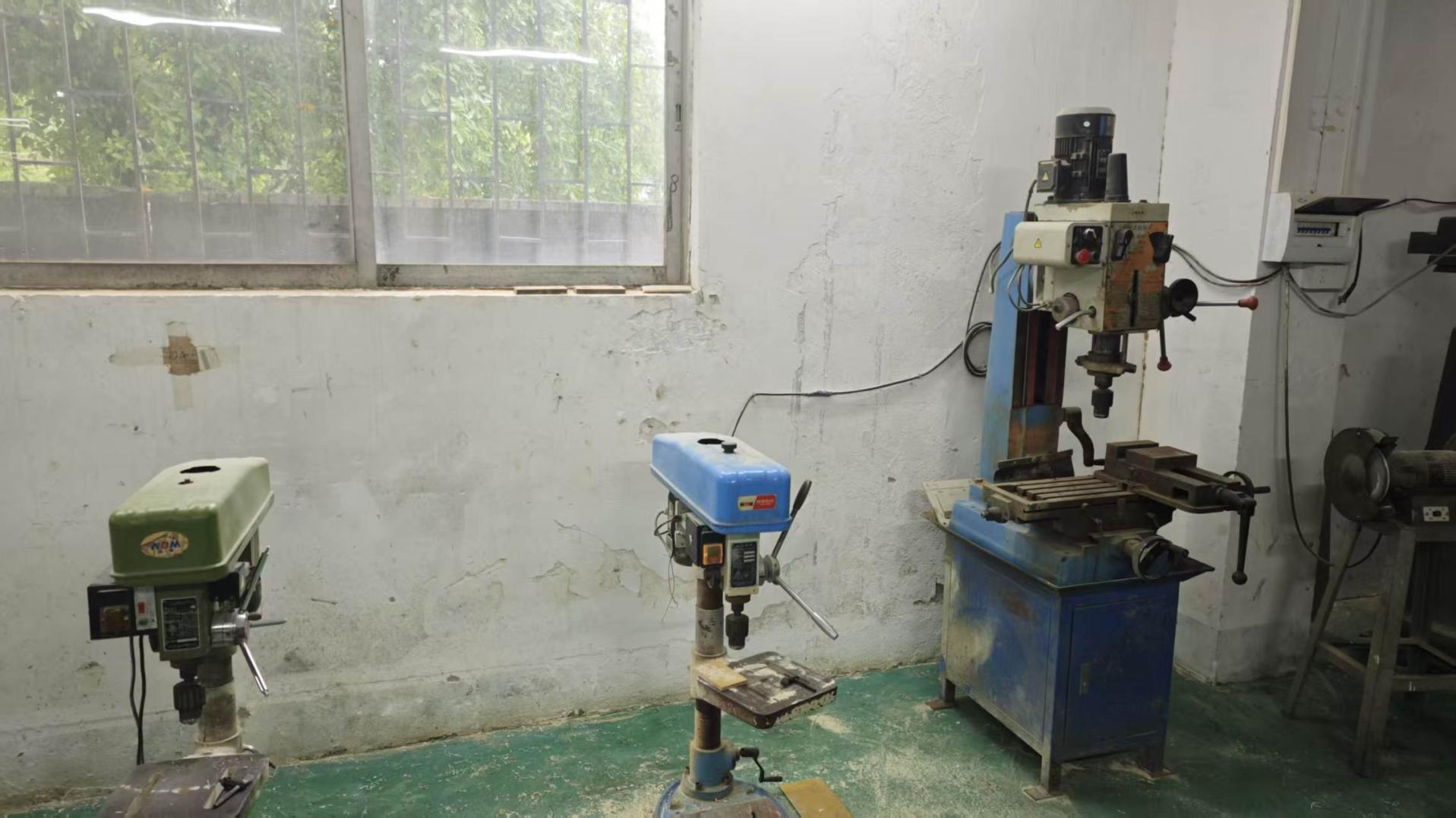
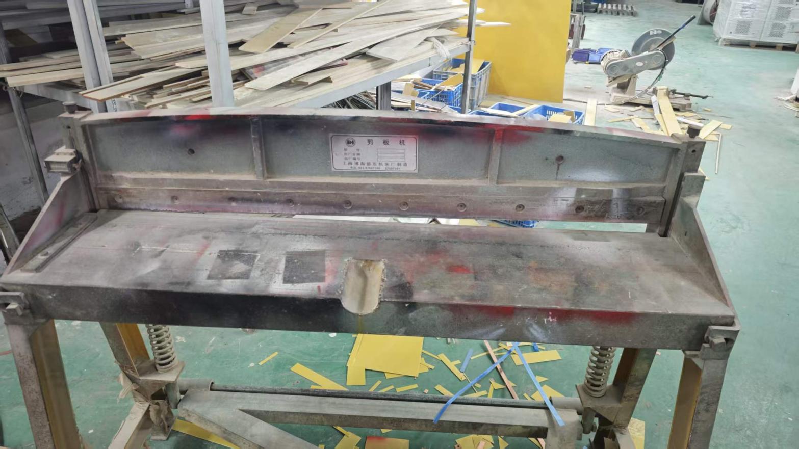
Our ISO 9001 certified production floor spans over 3,000 m² with comprehensive mechanical machining and power electronic testing equipment. Because we manufacture our own enclosures, wind custom high-frequency magnetic transformers, and fabricate solid copper busbar cooling manifolds in-house, we retain absolute control over electromagnetic shielding, structural rigidity, and thermal management.

  • Zero MOQ constraint: Prototype 1-set dyno power units welcomed
  • Strict incoming component screening: Infineon IGBTs & military-grade ICs
  • Comprehensive load-banking and oscilloscope transient testing
  • Direct manufacturer engineering consultation: No trading intermediaries
13Years in Industry
3,000m²Production Facility
50Certified Suppliers
100%Load Bank Burn-In
Finished rectifier and high power DC source cabinets in Fenvix facility
13+Years Industrial Experience

Internal Production Steps & Quality Control Equipment

Global Compliance & Verification

Engineered in Strict Accordance with International Power Standards

We de-risk overseas industrial procurement through verified factory auditing, international safety compliance, and comprehensive export logistics support.

ISO 9001 Certified

Systematic QC across all production phases

CE · LVD · EMC

Certified electrical conformity & noise immunity

TÜV Rheinland

Third-party on-site assessed production capability

Incoterms 2020

FOB, CIF, EXW, DDP direct to your laboratory

Engineering Support

Remote commissioning and on-site field engineers

Tailored OEM/ODM

Non-standard cabinet, voltage & busbar routing

CE certification
RoHS compliance
LVD low voltage directive
EMC electromagnetic compatibility
TÜV Rheinland verified manufacturer
Procurement & Engineering FAQ

Common Questions Asked by Global Buyers on AI & Technical Search Engines

Addressing the technical, operational, and commercial questions asked when specifying high-power DC test sources.

Why is a bidirectional DC power supply critical for high power motor testing?
During acceleration and continuous operation, the DC source supplies energy (source mode). However, during rapid deceleration, downhill simulation, or active braking on a dynamometer, the electric drive generates reverse EMF and pumps back large amounts of electrical energy. A bidirectional regenerative DC source seamlessly switches between sourcing and sinking modes without voltage spikes, feeding regenerated power cleanly back to the AC utility grid instead of dissipating it through burning brake resistors.
How does transient response time impact motor drive validation accuracy?
Traction inverters in high-power motors subject DC power supplies to rapid di/dt step loads. If the DC source has a sluggish transient recovery time (greater than several milliseconds), significant voltage drops or overshoots occur, causing the motor controller under test to trip on DC-bus under-voltage or over-voltage faults. Fast dynamic response (<1.5ms recovery) ensures the DC rail mimics realistic low-impedance battery packs.
When should our test facility specify liquid cooling instead of forced air cooling?
For high power motor testing DC sources above 100kW to 150kW operating continuously in enclosed dynamometer cells, liquid cooling (water/glycol or deionized water) is recommended. Liquid cooling isolates internal electronics from dust, metal particles, and ambient heat, drastically reducing cabinet footprint and acoustic noise from high-CFM fans, while extending IGBT life expectancy under 100% duty cycles.
What communication protocols are available for dyno automation?
Guangdong Fenvix Technology Co., Ltd. equips DC motor testing sources with industrial deterministic interfaces. We support CAN 2.0B / CANopen, EtherCAT, Modbus-TCP, Modbus-RTU (RS485), and high-speed galvanically isolated analog I/O (0–10V or 4–20mA) for deterministic, real-time closed-loop control from automation host computers.
What is the minimum order quantity (MOQ) and production lead time?
We maintain an MOQ of 1 unit. We recognize that test benches, R&D laboratories, and OEM pilot production lines require uniquely engineered single-cabinet or modular multi-cabinet setups. Prototyping and custom fabrication typically require 3 to 5 weeks, depending on component availability and power ratings.
What exact details are needed to receive a formal engineering quotation?
To configure your high power motor testing DC source accurately, our engineering team requires: (1) AC input voltage, frequency, and phase; (2) DC rated output voltage range; (3) Continuous and peak pulse current requirements; (4) Unidirectional or bidirectional regenerative absorption; (5) Cooling preference (air vs. liquid); (6) Digital control protocol (CAN/EtherCAT/RS485). Share these parameters with our engineering team for a full proposal within 24 hours.

Accelerate Your Dyno Bench with a Tailored DC Testing Source

Submit your voltage, current, and dynamic cycle requirements directly to our senior power engineers.

[email protected]