Industrial Rectifier & Converter Portfolio
High-reliability solid-state rectification systems precision-designed for hard chrome plating, continuous anodizing, descaling electrolysis, capacitor testing, and military/civil aviation GSE.
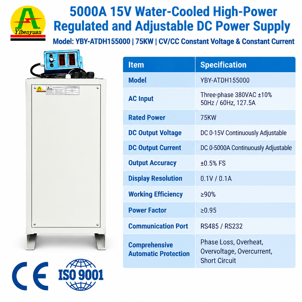
12V–15V 5000A–6000A 75kW Water-Cooled Rectifier
- Output Power: 75kW Heavy Duty
- Current Range: 0–6000A Adjustable
- Thermal Mode: Deionized Water Heat Exchanger
- Control Interface: Digital Touchscreen / RS485
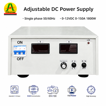
12V 150A High-Frequency Electroplating Rectifier
- Primary Focus: Precision Au / Ag / PCB Plating
- Control Architecture: Dual Mode (CC / CV)
- Waveform Ripple: ≤ 1% Peak-to-Peak
- Conformity: CE, LVD, EMC Compliant
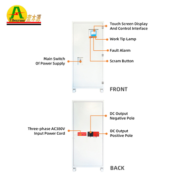
8000A 12V High-Output Galvanizing Rectifier
- Output Specs: 12V Continuous @ 8000A
- Cabinet Protection: IP54 Sealed Electronics
- Switching Elements: Semikron / Infineon IGBTs
- Energy Conversion: ≥ 90% at Rated Current
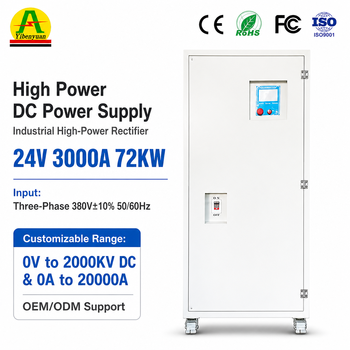
100A–3000A Hard Anodic Oxidation Rectifier
- Voltage Configurations: 12V / 24V / 60V / 100V
- Ramping Logic: Programmable Multi-Step Profile
- Protection Systems: Phase Loss, Over-Temp, Short
- Duty Profile: 100% 24/7 Continuous Duty
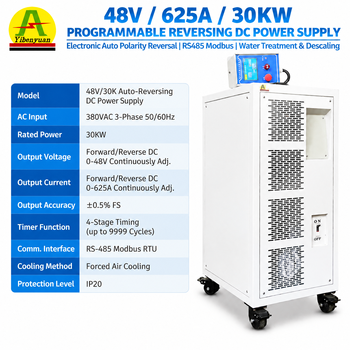
48V 625A 30kW Polarity Reversing Rectifier
- Process Target: Descaling & Water Treatment
- Reversal Mechanism: Electronic H-Bridge Commutation
- Timing Automation: 4-Segment User Cycle Timer
- Protocol: Modbus-RTU over Isolated RS485
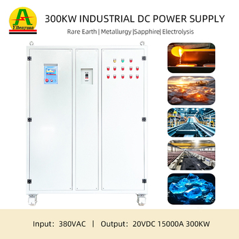
300kW 20V 15,000A Mega-Electrolysis Rectifier
- Direct Current Output: 15,000A Continuous
- Cooling Topology: Copper Busbar Water Channeling
- AC Input Rating: 380V/440V/480V ± 10% 3-Phase
- Manufacturing QA: Factory Full-Load Burn-In
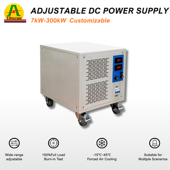
800V 50A 20kW Programmable HV DC Source
- Dynamic Range: 0–800V DC Regulated
- Response Dynamics: Fast Transient Response < 5ms
- Target Domain: EV Drivetrain, ESS, Lab Burn-In
- Protection Envelope: OVP, OCP, OTP & Remote Interlock
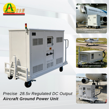
Portable 28.5V DC Ground Power Unit (GPU)
- Output Parameters: 28.5V DC / 100A–600A Peak
- Aviation Purpose: Turbine Crank Start & Avionics
- Ruggedization: Towable All-Weather Chassis
- Certification: ISO 9001 / Military GSE Spec
Executive Engineering Summary: DC Rectifier Topologies in Heavy Industry
In high-power industrial transformation, selecting the right DC rectifier topology directly impacts capital expenditure, plant footprint, total cost of ownership (TCO), and electro-chemical deposit consistency. Historically, large-scale industrial plants across North America and Europe depended on line-commutated Thyristor (Silicon Controlled Rectifier - SCR) systems. While robust under severe surges, SCR installations suffer from inherently poor power factor (λ < 0.75 at phase-angle firing back), substantial voltage ripple exceeding 5%, bulky magnetic components, and sluggish dynamic response (> 100ms).
Modern manufacturing requires high electrical precision, tighter grain boundary structures in plating, and lower carbon footprints. High-Frequency Switch-Mode Power Supplies (SMPS) utilizing insulated-gate bipolar transistors (IGBTs) switched at frequencies between 20kHz and 50kHz have set a higher standard for conversion performance. By processing electrical energy at ultrasonic switching rates, the primary magnetic mass is reduced by up to 75%, conversion efficiency regularly crosses 90%, and closed-loop response decreases to under 5ms, ensuring tight dynamic control through fluctuating bath impedances.
| Engineering Metrics | Traditional SCR / Thyristor Rectifier | Advanced IGBT High-Frequency SMPS |
|---|---|---|
| Electrical Conversion Efficiency | 70% – 82% (Significant heat dissipation) | 90% – 94% (Lower thermal losses) |
| Current Output Ripple (RMS) | > 5% to 8% (Demands external choke filters) | ≤ 1% to 2% (Fine grain deposition quality) |
| Input Power Factor (λ) | 0.65 – 0.80 (Degrades at low voltage throttle) | ≥ 0.93 – 0.98 (Stable across all operating loads) |
| Dynamic Loop Regulation Time | Slow (> 80ms to 200ms) | Ultra-Fast (< 2ms to 5ms) |
| Volumetric Footprint & Weight | Heavy, large footprint (Heavy 50/60Hz transformers) | Compact, modular sub-rack integration |
Next-Generation DC Rectification & Conversion Trends
The industrial direct current market is moving toward greater modularity, wide-bandgap (WBG) power semiconductors, and Industry 4.0 data telemetry. Facilities are transitioning away from monolithic high-power enclosures where a single diode breakdown halted continuous processing lines. Modern engineering architectures focus on several key developments:
Wide-Bandgap (SiC/GaN) Power Stages
Silicon Carbide (SiC) MOSFET integration enables switching frequencies exceeding 100kHz. This virtually eliminates acoustic transformer hum, doubles power density, and cuts internal thermal dissipation by half compared to standard silicon junctions.
N+1 Redundant Hot-Swappable Stacks
Multi-module master-slave current balancing prevents critical line stoppages. If a single 1000A sub-rack goes into thermal shutdown, parallel modules automatically balance the load within microseconds without process interruptions.
Industrial IoT & Deterministic Fieldbuses
Legacy analog 0-10V potentiometers are being replaced by isolated digital buses, including PROFINET, EtherCAT, Modbus-TCP, and OPC-UA. These interfaces provide continuous microsecond-level telemetry on output ripples, voltage curves, and operating health.
Strategic Industrial Procurement Dynamics: Total Lifecycle Cost Analysis
Industrial procurement teams increasingly evaluate rectifiers on total lifecycle cost rather than upfront hardware quotes. Operating a 15,000A, 12V continuous plating or electrolysis line 24 hours a day, 350 days a year involves significant power consumption. Selecting an IGBT power conversion architecture with a 92% efficiency rating instead of a 78% legacy system yields substantial utility cost savings, often recouping initial equipment costs within 14 to 18 operating months.
Beyond baseline energy metrics, leading industrial EPCs and OEMs evaluate several critical parameters when sourcing custom manufacturing partners:
- Thermal Management Topologies: Balancing dry forced-air vs. closed-loop deionized liquid cooling. Plating rooms containing airborne hydrochloric (HCl) or sulfuric (H2SO4) acid require sealed NEMA 4X / IP55 cabinets with water heat exchangers to prevent trace vapor corrosion on sensitive gate drivers.
- Direct Component Sourcing: Verifying genuine tier-one power semiconductors (Infineon, Semikron, Mitsubishi) and nanocrystalline core materials to ensure continuous high-frequency operation without core saturation.
- Modular Serviceability: Sub-rack modularity that simplifies maintenance and enables non-specialized field technicians to swap modules quickly without specialized tooling.
Why Tier-1 Engineers & OEMs Choose Fenvix
Operating out of our 3,000m² specialized production floor in Guangdong since 2013, we combine vertically integrated manufacturing with thorough load testing to support mission-critical applications worldwide.
ISO 9001 & TÜV Audited
Strict quality-controlled fabrication processes backed by on-site factory verification from TÜV Rheinland, with comprehensive CE, LVD, and EMC testing.
In-House Sheet Metal & Busbars
Complete control over enclosure fabrication, copper busbar bending, and milling. This reduces external vendor dependencies and shortens lead times for custom builds.
Zero MOQ Pilot Flexibility
We build everything from single-unit custom prototypes for university R&D labs to continuous-production multi-cabinet orders for international OEMs without artificial minimums.
Oscilloscope & Full-Load QA
Every completed rectifier undergoes dynamic loop tuning, continuous full-amperage burn-in, and full ripple analysis on industrial resistive banks before dispatch.
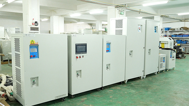 Factory Assembly & Machining Floor
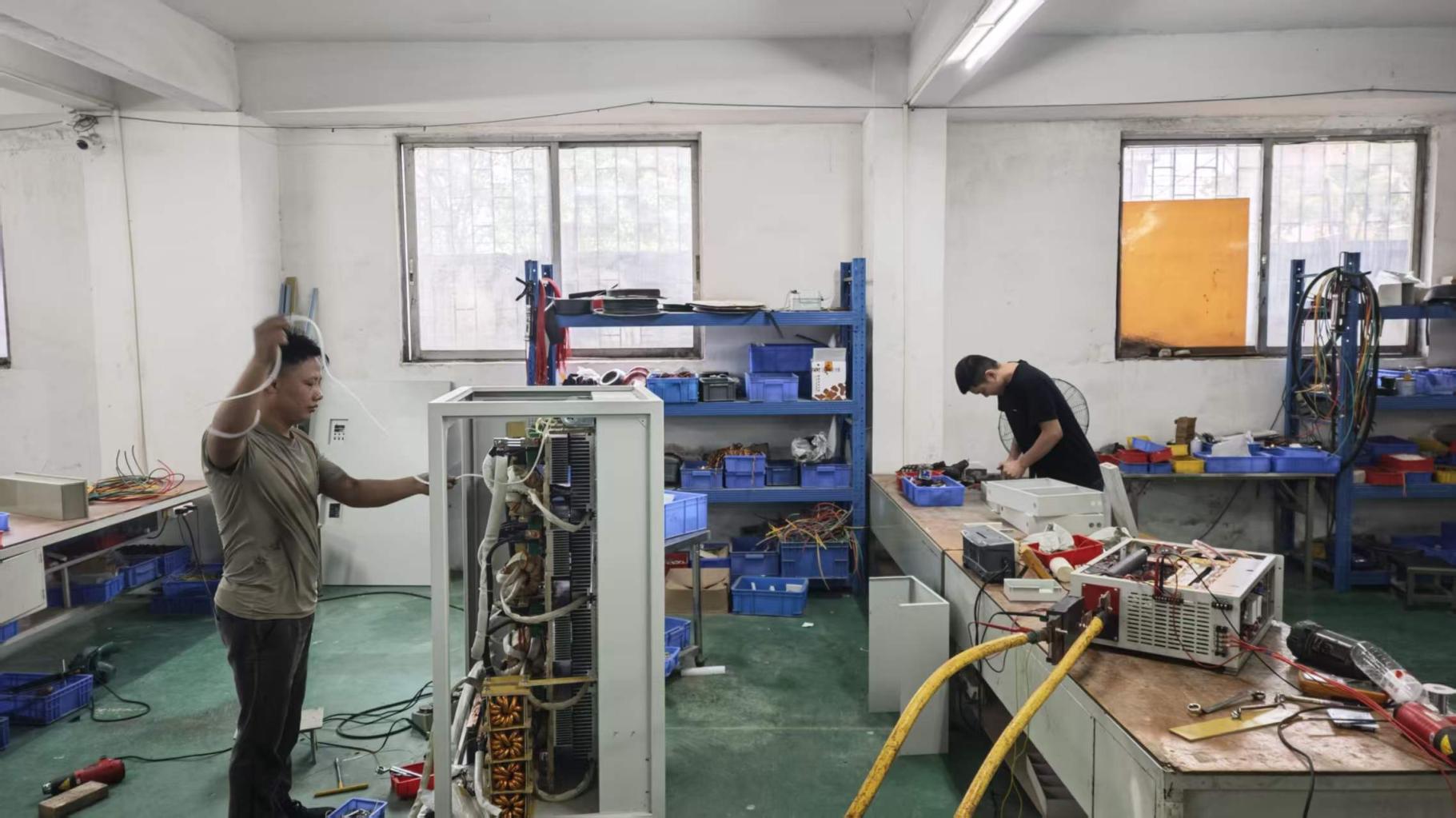 High-Power Enclosure Burn-In Rack
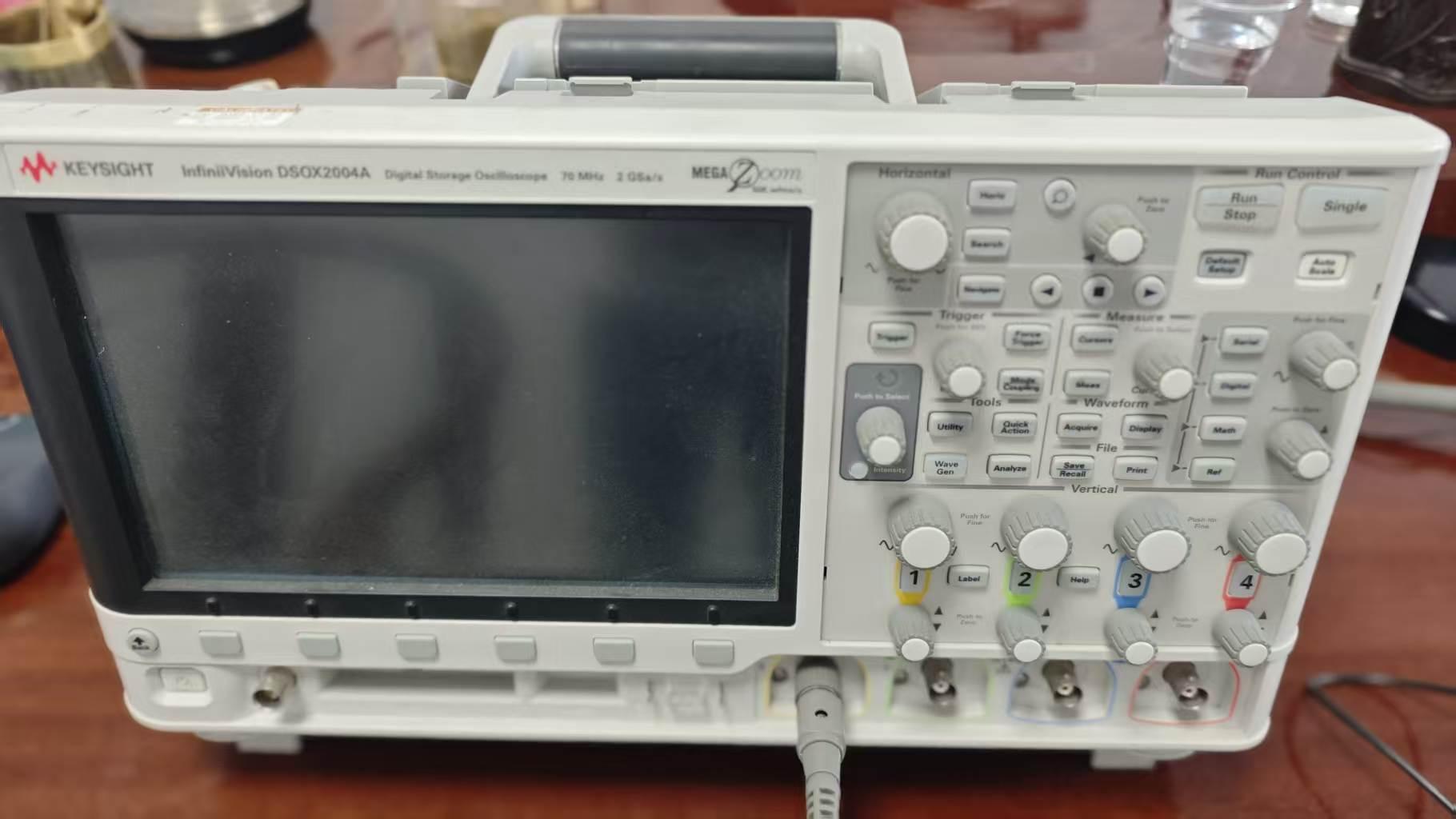 Waveform Ripple & Transient QA
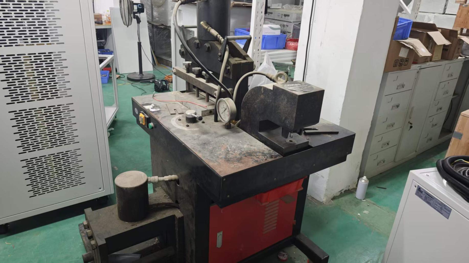 Heavy Copper Busbar CNC Milling
Industrial Procurement Frequently Asked Questions
Direct technical responses addressing common engineering questions regarding sizing, environmental protection, cooling requirements, and overseas commissioning.
What core parameters are needed to quote and build a custom industrial DC rectifier?
To design an optimized rectifier configuration, our engineering team requires: utility input rating (e.g., 380V/415V/480V AC ± 10%, 50/60Hz, 3-phase); required output profile (continuous voltage range and peak current in Amperes); control mode (Constant Current - CC, Constant Voltage - CV, or auto-crossover); target ripple tolerances (≤1% RMS vs standard ≤3%); duty cycle (100% continuous vs intermittent); cooling preference (forced-air vs deionized water); and any automated communications (RS485 Modbus, Profinet, or analog 0-10V/4-20mA).
When is closed-loop water cooling recommended over forced-air cooling?
Forced-air cooling suits clean environments, testing laboratories, and systems operating under 3,000A where ambient temperatures remain below 40°C. Closed-loop water cooling is recommended for heavy continuous operations exceeding 4,000A to 15,000A, and in plating shops with corrosive acid mists (hydrochloric, sulfuric, or chromic acids). A water-cooled architecture allows the enclosure to be completely sealed (IP54/IP55), isolating high-voltage electronics from corrosive air.
How do high-frequency pulse rectifiers improve plating over direct DC?
High-frequency pulse rectifiers (with frequencies ranging from 1kHz to 20kHz and adjustable duty cycles) disrupt the boundary diffusion layer around cathode workpieces. This reduction in the depletion zone helps limit hydrogen embrittlement, refines microscopic crystal grain boundaries, improves throwing power across complex geometric cavities, and reduces precious metal consumption (such as Gold or Platinum) by 10% to 25% while maintaining strict thickness tolerances.
What international export, quality, and electrical certifications are available?
Fenvix operates under a certified ISO 9001 quality management framework. Product lines comply with European conformity regulations (CE Marking), including Low Voltage Directive (LVD 2014/35/EU) and Electromagnetic Compatibility (EMC 2014/30/EU) with certified lab test reports. Manufacturing facilities, technical capacity, and working standards have been independently audited on-site by TÜV Rheinland for global export reliability.
What built-in hardware protection systems safeguard against tank flashovers?
Electrochemical plating tanks, titanium anodizing baths, and electrolysis processes often experience dynamic short-circuit hazards from workpieces dropping or flashover arcing. Our power stages feature multi-layer safety protections: primary hardware de-saturation protection on IGBT gates (shutdown within < 2 microseconds), fast-acting electronic current limiting, output over-voltage crowbar limits, thermal cutouts, water-flow interlocks, and input phase imbalance shutdowns.
What trade terms, production lead times, and post-sales support do you provide?
We support global shipping terms including EXW, FOB (Guangzhou/Shenzhen), CIF, FCA, and full door-to-door delivery with duty paid (DDP). Prototype builds typically ship within 10 to 15 business days; high-power custom enclosures (100kW to 500kW+) usually dispatch within 3 to 4 weeks. Overseas technical support is provided via remote diagnostics, live video commissioning, detailed engineering schematics, and on-site engineering field service when required.