[email protected]
ISO 9001 Certified Manufacturer Exporting to 4 Continents

Custom OEM Variable DC Power Supply Manufacturers & Factories

Precision High-Power Topologies, High-Frequency IGBT Rectifiers, and Solid-State Conversion Architecture Engineered for Mission-Critical Surface Engineering, Electromobility Testing, and Heavy Chemical Synthesis.

Precision-Engineered Variable DC Power Supplies & Rectifiers

Manufactured under rigorous ISO 9001:2015 frameworks in Guangdong. Designed for non-standard voltage windows, extreme dynamic step loads, and ultra-low ripple requirements.

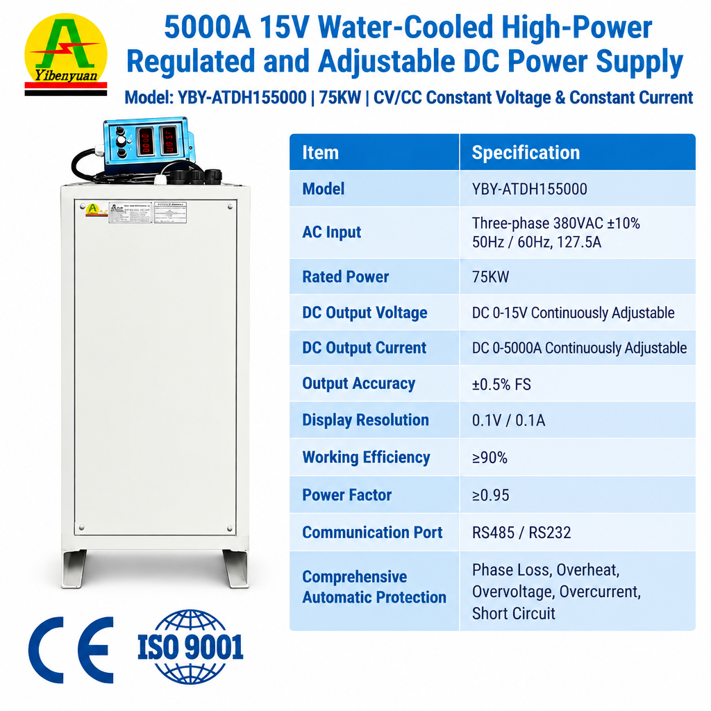
Heavy Electrolysis 12V 15V 5000A 6000A 75KW Water Cooled High Frequency Electroplating Rectifier

12V–15V 5000A–6000A 75kW Water-Cooled DC Rectifier

  • TopologyHigh-Frequency IGBT
  • Cooling MatrixDeionized/Chilled Water
  • Operation ModesConstant Voltage / CC
  • Control InterfaceRS485 Modbus-RTU
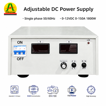
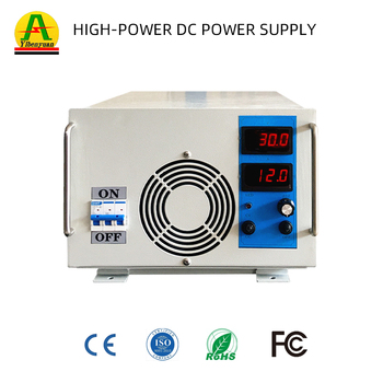
PCB & Precision Plating 12V 150A High Frequency Electroplating Rectifier

12V 150A Precision High-Frequency Plating Source

  • Ripple Factor≤ 1% RMS Peak-to-Peak
  • Target FinishAu, Ag, Cu Fine Pitch
  • Regulation±0.5% Load Regulation
  • ComplianceCE, LVD, EMC Verified
Heavy Galvanizing 12V 4000A 48KW High Frequency Electroplating Rectifier

12V 4000A 48kW Industrial Surface Rectifier

  • Efficiency≥ 90% at Rated Full Load
  • Duty CycleContinuous 24/7/365
  • Input Line380V/415V/480V 3-Phase
  • EnclosureSealed Anti-Corrosion IP54
Ultra High Current 8000A 12V Water Cooled Electroplating Rectifier

8000A 12V Water-Cooled Multi-Pulse Rectifier

  • Busbar MaterialT2 Solid ETP Copper
  • ProtectionOver-Temp, Phase-Loss, Short
  • Dynamic Response< 5ms Step Recovery
  • Control TypePLC / Remote Digital Touch
EV & Powertrain 800V 400V 50A 20KW High Voltage Adjustable DC Power Supply

800V 50A 20kW Programmable DC Test Supply

  • Output Range0–800V DC Continuously Adj.
  • Slew RateProgrammable Voltage Ramping
  • ApplicationEV Battery Pack & Inverter Test
  • InterfaceLAN, CAN, RS485 Isolated
Pulse Hard Anodizing Titanium alloy anodizing power supply 150V 50A

150V 50A Titanium Alloy Anodizing Power Unit

  • Voltage RampMulti-Segment Time Control
  • Layer DensityHigh Dielectric Oxide Growth
  • Cooling SystemForced Direct-Tunnel Airflow
  • Safety Isolation3.5kV Input/Output Galvanic
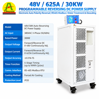
Electrochemical Cleantech 48V 625A Auto Polarity Reversing DC Power Supply

48V 625A 30kW Polarity-Reversing DC Supply

  • Reversal CycleIntegrated Hardware H-Bridge
  • Dead-Time ControlMicrosecond Arc-Free Switching
  • Industrial TargetDescaling & Advanced Oxidation
  • Control ProtocolEmbedded Touchscreen Timer
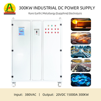
Megawatt Chlor-Alkali 300kW 20V 15000A Water-Cooled DC Power Supply

300kW 20V 15000A Megawatt Electrolysis Rectifier

  • Output TopologyModular Paralleled N+1 IGBT
  • Cooling SystemIntegrated Dual-Circuit Liquid
  • Efficiency Factor93.5% at Sustained Operating Peak
  • Safety SystemArcing, Over-Flux & Surge Trip

Technological Architecture: The Industrial Paradigm Shift in DC Topologies

Analysis of switching dynamics, semiconductor material transitions, and thermal balancing configurations defining current variable DC power systems.

The Demise of SCR Thyristors vs High-Frequency IGBT Topologies

Legacy variable power supplies heavily utilized Silicon-Controlled Rectifier (SCR) phase-control topologies operating at line frequencies (50/60 Hz). While mechanically robust, SCR systems exhibit structural inefficiencies: high low-frequency ripple factors (typically requiring massive inductive filtering), poor displacement power factors (<0.75 under light phase-angle delay firing), and slow transient step recovery (>50ms).

Fenvix High-Frequency IGBT systems switch at 20 kHz to 40 kHz, reducing physical magnetic footprint by 65% and stabilizing line regulation to ±0.5%.

The implementation of planar magnetic cores and primary-chopped PWM bridges enables microsecond-level feedback loops, mitigating output arc discharge in anodizing tanks and semiconductor wafer electro-deposition systems.

Wide Bandgap Transition: Silicon Carbide (SiC) & GaN Integration

The standard silicon (Si) insulated-gate bipolar transistor is nearing fundamental theoretical thermal-breakdown limits in extreme high-density envelopes. The power supply manufacturing sector is aggressively pivoting toward Silicon Carbide (SiC) MOSFETs and Gallium Nitride (GaN) high-electron-mobility switching stages for programmable test gear.

SiC allows operating junction temperatures exceeding 175°C with a 70% decrease in reverse recovery charge (Qrr).

For custom OEM buyers, this shifts power supply densities from legacy levels of 5 kW per standard rack unit to over 15 kW/U, vital for automated test equipment (ATE) racks, aerospace power emulation, and EV traction sub-assembly burn-in benches.

Thermal Dissipation Dynamics: Liquid-Cooled vs. Forced-Air Matrices

Thermal management is the single largest determinant of MTBF (Mean Time Between Failures) in high-capacity DC power units. Forced-air cooling forces harsh environmental contaminants—acid mist, suspended nickel particles, alkaline moisture—directly across active gate drivers and primary inductors, leading to dielectric tracking and catastrophic busbar flashover.

Fenvix deionized liquid-cooled plates run heat extraction circuits directly through insulated copper cold-plates sealed inside IP54/NEMA 4X enclosures.

This design isolates high-power stages completely from airborne halogens, ensuring round-the-clock reliability in severe chemical electroplating and metallurgical refining facilities.

Architecture Metric Legacy SCR / Thyristor Phase Control Hard-Switched Silicon IGBT Fenvix Soft-Switching Resonant SiC/IGBT
Typical Conversion Efficiency 72% – 81% (High heat dissipation) 87% – 91% (Standard industrial) 93.5% – 96.2% (High-efficiency operational savings)
Current Ripple (Peak-to-Peak) 5% – 12% without massive external choke 2% – 4% at high switching speeds ≤ 0.5% – 1.0% (Optimum crystal lattice deposition)
Dynamic Load Response (10%-90%) 50ms – 100ms (Line frequency bound) 8ms – 15ms < 1.5ms (Instantaneous pulse capability)
Enclosure Cleanliness Requirement Forced airflow requiring frequent filter servicing Positive-pressure air tunnel Hermetically Sealed IP54 Liquid-Cooled Chambers
Total Cost of Ownership (5-Yr Span) High energy overhead + high line losses Moderate maintenance & replacement parts Lowest TCO via power savings & minimal downtime

Future Sourcing Trends for Global B2B Power Electronics Buyers

Actionable intelligence for engineering teams and international procurement officers sourcing industrial DC power solutions through 2026–2030.

Modular Scalability & Active N+1 Redundancy

Global operations no longer tolerate single-point-of-failure monolithic cabinet architectures. Modern plant blueprints require variable DC units constructed from hot-swappable 15kW, 30kW, or 50kW sub-racks tied in active master-slave droop control.

If an internal switching bridge suffers an over-temperature degradation, the primary controller instantaneously sheds non-critical load margins and balances current sharing across the remaining sub-units without line interruption, ensuring process continuity in high-value wafer fab lines.

Native Fieldbus Integration & Predictive IIoT Telemetry

Isolated analog 0-10V/4-20mA potentiometric control is swiftly moving to obsolete status in Industry 4.0 specifications. High-tier industrial supply contracts mandate native high-speed bus interfaces: Ethernet/IP, Profinet, EtherCAT, and Modbus-TCP alongside deterministic CAN interfaces.

OEM power supplies now serve as primary IoT sensory arrays, measuring output electrolyte impedance variations, internal capacitor ESR drift, and thermal gradients across heatsinks to predict component end-of-life before physical failure occurs.

Bi-Directional Power Flow & Active Front Ends (AFE)

Testing large battery energy storage modules (BESS), bidirectional on-board chargers (OBC), and regenerative electric drives demands power sources that perform seamless two-quadrant operation.

Active Front End (AFE) rectifiers are mandatory to maintain Total Harmonic Distortion (THDi) below 3% while delivering unit power factors (>0.99). When operating in sink/load mode, these systems invert DC energy back onto the factory 3-phase AC distribution grid with 92%+ regenerative efficiency, significantly lowering operating overhead.

Why Tier-1 Industrial Integrators Partner With Fenvix

Combining heavy mechanical fabrication, advanced magnetic component winding, and precision embedded firmware programming within an ISO 9001:2015 audited facility in Guangzhou, China.

13+
Years Engineering Track
3,000m²
Controlled Plant Floor
15,000A
Max Single-System Output
Zero
Strict MOQ Requirements

End-to-End Mechanical & Electrical Co-Design

Unlike assembly houses that buy generic sheet enclosures and stock switchgear, Fenvix maintains in-house shearing, punch-press tooling, milling, and precision automated tapping facilities. We design and build heavy T2 copper busbars, custom high-isolation transformers, and optimized water manifold layouts directly within our production facility.

Comprehensive Verification & Third-Party Audit

Our operational management is certified to ISO 9001:2015, and our facility has completed thorough on-site verification audits conducted independently by TÜV Rheinland. Export units meet relevant CE compliance directives (Low Voltage Directive 2014/35/EU, EMC Directive 2014/30/EU) and RoHS standards, accompanied by detailed factory acceptance test reports.

Direct Global Trade & Engineering Support

We eliminate friction for international procurement teams by supporting direct multi-currency settlement (USD, EUR, GBP, AUD, JPY, CAD, CHF, CNY) and offering comprehensive trade terms from EXW/FOB to full DDP delivery. Our bilingual application engineering team reviews technical specifications, duty cycles, and integration requirements within 24 hours.

Frequently Asked Questions: Technical Sourcing & OEM Configuration

Clear, direct technical answers regarding topology configuration, dynamic stability, and global procurement procedures.

What technical parameters are critical to provide for an exact custom OEM quotation?
To size the internal semiconductor matrix, transformer kVA, and cooling circuits accurately, our engineering team requires:
  • AC Input Specifications: Supply voltage (e.g., 208V, 380V, 415V, 480V), phase configuration (single or 3-phase), and grid frequency (50Hz or 60Hz).
  • DC Output Profile: Nominal and peak voltage, adjustable span (e.g., 0–15V, 0–800V), and rated output current (e.g., 150A to 15,000A).
  • Operating Modes: Constant Voltage (CV), Constant Current (CC), automatic crossover, or pulsed square-wave duty profiles.
  • Ripple & Precision Demands: Permissible current/voltage ripple (RMS vs. Peak-to-Peak percentage) at minimum and maximum operating loads.
  • Operational Environment & Duty: Continuous 100% duty cycle vs. intermittent testing, ambient shop temperature, presence of corrosive chemistry, and preferred cooling media (forced air vs. closed-loop water).
  • Communication Interface: Modbus-RTU (RS485), Profinet, Ethernet/IP, or isolated 0–10V analog automation loops.
How does Fenvix guarantee thermal stability and current sharing in paralleled modules?
High-current units (above 3000A) and high-power setups (up to 300kW+) use decentralized active dynamic current-sharing architecture. Rather than relying solely on passive resistive balancing, our proprietary control boards continuously monitor each IGBT leg's collector-emitter voltage (Vce_sat) and individual hall-effect current sensors. High-speed microcontrollers adjust the pulse-width modulation (PWM) carrier phases dynamically, maintaining inter-module current sharing balance within ≤1.5% across the entire 10% to 100% load envelope.
When is a water-cooled rectifier necessary compared to forced-air convection?
Forced air cooling is economical and straightforward for general electronics test benches, laboratory R&D, and cleanroom automated test equipment under 15kW. However, closed-loop water cooling is essential under three specific operational conditions:
  1. Corrosive Environments: Electroplating, hard anodizing, and electrowinning facilities generate airborne sulfuric, hydrochloric, or chromic acid mists that quickly corrode air-cooled heatsinks and cause dielectric tracking across PCBA tracks.
  2. High Power Envelopes: Above 50kW or 3,000A, the fan noise, airflow requirements, and cabinet volume of air-cooled equipment become unwieldy. Liquid cooling extracts heat efficiently via compact chillers.
  3. Sealed Enclosure Requirements: Facilities requiring sealed IP54 or NEMA 4 enclosures to completely lock out dust, moisture, and ambient industrial airborne particulates.
What testing protocols are executed prior to factory dispatch and export shipping?
Every Fenvix power system undergoes rigorous Factory Acceptance Testing (FAT) before crating:
  • Dielectric Withstand Testing (Hi-Pot): Primary AC input to chassis and secondary DC output to chassis tested up to 2.5kVAC / 3.75kVDC to verify galvanic isolation.
  • Full-Load Thermal Soak: Sustained burn-in at maximum rated power against calibrated resistive and regenerative dynamic load banks.
  • Ripple & Noise Spectral Analysis: High-bandwidth oscilloscope verification of peak-to-peak ripple across the complete voltage span.
  • Transient Step Load Response: 10% to 90% step perturbation testing to verify voltage undershoot, overshoot, and microsecond loop settling times.
Factory test reports, schematics, and terminal point documentation are provided with every shipment.
What are the lead times for custom non-standard prototypes versus volume batch runs?
Because sheet-metal processing, busbar stamping, transformer assembly, and firmware programming occur within our own facilities, standard prototype builds typically ship within 3 to 4 weeks from mechanical drawing sign-off. High-power systems (100kW to 300kW+) or fully specialized liquid-cooled cabinets generally require 5 to 6 weeks. Batch OEM production agreements are supported by strategic staging of long-lead power semiconductors and core magnetics to enable regular scheduled deliveries.

Discuss Your Custom DC Power Supply Requirements

Send your voltage parameters, peak current, regulation tolerances, and application specs directly to our senior power systems design team for a rapid engineering evaluation and direct quotation.